
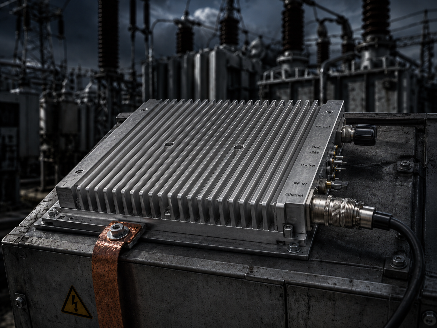
Engineers deploying VSAT communications inside electrical substations face brutal electromagnetic realities. High-voltage switching creates massive ground potential rise, forcing transient currents through sensitive monitoring cables. This article provides pure engineering truth regarding RF uplink isolation. We analyze specific hardware defenses required for stable transmission environments.
1. The Reality of Substation RF Link Failures
Substation environments destroy poorly isolated electronic equipment daily. Large inductive kickbacks happen frequently during primary breaker switching sequences. These switching events inject massive transient currents directly into local earth grounds. Field technicians constantly report bizarre communication dropouts matching these electrical grid events exactly. System integrators notice Ethernet monitoring screens freezing randomly while VSAT links suddenly lose phase lock.
What’s the real story? Commercial satellite modems lack sufficient galvanic isolation for this industrial chaos. When transient voltage spikes hit poorly bonded antenna masts, return currents seek paths of least resistance. These parasitic currents travel down communication cable shields straight into weak-current RJ45 monitoring pins. Ethernet controllers burn out or register false alarm states immediately. Satellite block upconverters (BUCs) drop output power because false telemetry triggers internal protection circuits arbitrarily. True engineering requires isolating these interfaces physically and electromagnetically. We measure these catastrophic shield currents using high-frequency clamp meters during grid switching operations. Values often exceed ten amps momentarily. Such current destroys standard commercial networking ports instantly.
Table of Common Fault Modes
| Fault Condition | Equipment Symptom | Root Cause |
| Transient Ground Rise | RJ45 port failure | Current seeking ground via ethernet shield |
| Breaker Switching | Sudden VSAT link drop | Phase noise corruption from ground loop |
| Poor Mast Bonding | False temperature alarm | ADC reference voltage shift |
2. Ground Potential Rise and RF Chassis Dynamics
Understanding ground loop physics remains mandatory for designing survivable communication nodes. Ground potential rise occurs whenever massive electrical faults dump energy into substation earth mats. Different physical locations across a single facility develop vastly different voltage potentials temporarily. Antenna pedestals often sit far away from main control room grounds. This physical separation creates dangerous voltage differentials between equipment chassis.
Here’s the deal: connecting these two locations with copper cables guarantees current flow. Coaxial cable shields and Ethernet drain wires become unintended high-current conduits. An RF amplifier bolted firmly onto a steel mast becomes part of this parasitic circuit loop. When operators use portable spectrum analyzers during maintenance, noise floors jump erratically during these current surges. Common-mode interference saturates input stages across delicate receiving equipment. Resolving this requires absolute strictness regarding single-point grounding architectures. We mandate isolating digital telemetry lines from RF chassis grounds using specialized aviation-grade interconnects. High-power amplifiers must handle large thermal loads without compromising this electrical isolation boundary.
Potential Difference Measurements
| Location Pair | Steady State | Transient Event |
| Control Room – Mast | < 0.5 Volts | > 50 Volts |
| Rack Ground – BUC Chassis | < 0.1 Volts | > 15 Volts |
| IF Cable Shield – Earth | < 10 mA | > 5 Amps |
3. Analyzing IF Input Vulnerabilities in Ku-Band Systems
Modern satellite communication relies heavily upon precise intermediate frequency (IF) signaling. Ku-band uplink modules typically receive multiplexed signals containing L-band data and reference clocks. The standard IF frequency range spans 950 MHz – 1450 / 1700 MHz. System controllers also inject a critical 10 MHz reference signal via this exact same IF port. This 0 dBm ±5 reference frequency dictates entire transmission stability profiles.
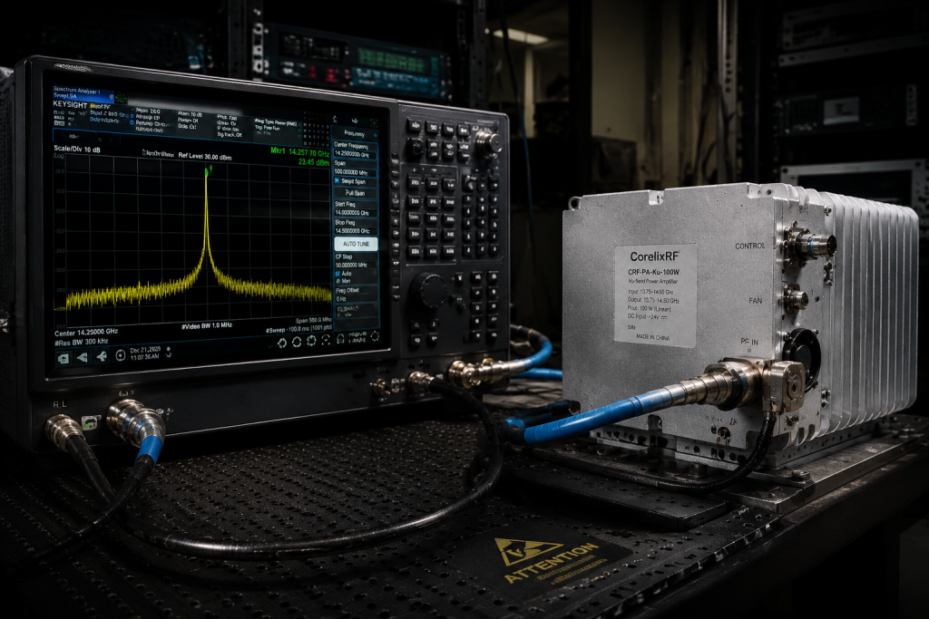
This is where it gets interesting… Ground loop currents traveling along IF cable shields corrupt this delicate 10 MHz timing signal completely. Modulated common-mode noise introduces severe phase jitter into local oscillators. VNA measurements reveal severe high-frequency roll-off when shield currents exceed minimal thresholds. The CRF-BUC-Ku-100W utilizes heavily filtered N-F input connectors specifically combating this degradation. Internal DC blocking capacitors prevent low-frequency ground currents from entering sensitive mixing stages. Amplifiers requiring 68 dB of small signal gain cannot tolerate noisy reference clocks. Gain flatness must remain strictly within ±0.6 dB per 40 MHz bandwidth. Any external electrical interference destroys these tight operating tolerances instantly.
IF Port Electrical Specifications
| Parameter | Specification | Purpose |
| IF Frequency Range | 950 – 1450 / 1700 MHz | Signal Input |
| Reference Frequency | 10 MHz, 0 dBm ±5 | LO Synchronization |
| Small Signal Gain | ≥68 dB | System Amplification |
4. Thermal and Power Dissipation Realities in High-Current Zones
Operating high-power RF equipment inside enclosed industrial spaces introduces severe thermal management challenges. Ku-band solid-state amplifiers draw significant electrical current during continuous wave transmission. Typical power consumption reaches 450 W during normal 50 dBm output operations. Substation environments often lack climate control infrastructure near antenna installations. Ambient operating temperatures easily swing between -40 °C and 60 °C.
You might be wondering: how do engineers manage this heat while maintaining electrical isolation? CorelixRF utilizes isolated 48 V (36 – 72 V) DC supply voltages feeding internal switching regulators. We deliver power via robust three-pin aviation connectors. These ruggedized mating connectors prevent accidental disconnections during heavy structural vibrations. Supplying 450 watts requires thick gauge wiring inherently susceptible to inductive coupling. Routing power cables alongside poorly shielded telemetry lines guarantees inductive cross-talk. Proper installation demands strict physical separation between high-current DC supplies and Ethernet monitoring cables. Internal thermal protection circuits monitor transistor temperatures continuously. False telemetry triggers from ground loops might shut down power unnecessarily without isolated monitoring pins.
Power and Thermal Parameters
| Characteristic | Value | Notes |
| Supply Voltage | 48 V (36 – 72 V) | DC Operation |
| Power Consumption | 450 W typical | At rated power |
| Operating Temperature | -40 to 60 °C | Harsh environment rating |
5. The CorelixRF Solution: CRF-BUC-Ku-100W Architecture
Engineering reliable substation communication demands purpose-built RF hardware architectures entirely. Standard commercial grade amplifiers fail miserably under continuous industrial electrical stress. The CorelixRF CRF-BUC-Ku-100W provides a heavily shielded transmission solution specifically designed for hostile environments. This module operates across standard 13.75 / 14 – 14.5 GHz Ku-band frequencies natively.
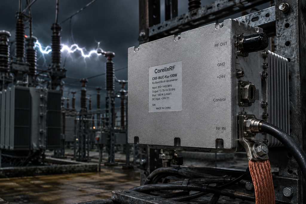
Ready for the good part? We guarantee a saturated output power exceeding 50 dBm. This 100 W rated capability ensures robust link margins cutting through heavy weather fade. Our engineers integrated a built-in high-power isolator protecting sensitive output stages from severe antenna mismatch. When substation ground faults cause transient VSWR spikes across transmission lines, internal components survive. The architecture includes comprehensive alarm and protection functions monitoring temperature and current independently. Ground loops cannot trigger false protection states because our internal sensor arrays utilize optical isolation barriers. This physical separation ensures monitoring logic remains completely decoupled from external chassis potentials.
Core RF Output Specifications
| RF Parameter | Minimum | Typical / Rated |
| Frequency Range | 13.75 GHz | 14.5 GHz |
| Output Power | ≥50 dBm | 100 W rated |
| Gain Stability | ±2 dB over temp |
6. Aviation-Grade Interconnects for Ethernet Monitoring
Network monitoring represents a massive vulnerability point for high-voltage installations. Standard RJ45 plastic connectors melt under extreme temperature variations or shatter during mechanical impacts. More importantly, standard Ethernet jacks provide zero defense against common-mode shield currents. Substation monitoring protocols require continuous Ethernet polling for equipment status verification.
Want to know a secret? The CRF-BUC-Ku-100W abandons consumer plastic interconnects entirely. We utilize a specialized aviation connector housing an RJ45 interface. This metallic aviation shell provides superior mechanical mating strength and environmental sealing. Internal Ethernet magnetics feature high-voltage isolation transformers blocking ground potential differences. Weak-current pins remain protected from large current return interference flowing across equipment racks. System integrators simply connect standard armored network cables into this ruggedized aviation port. Ethernet monitoring protocols report accurate telemetry data regardless of external substation electrical storms. We eliminate false triggering issues by fixing the hardware layer physically.
Communication Interface Details
| Interface Type | Hardware Format | Purpose |
| Monitoring Method | Ethernet | Remote telemetry |
| Connector Shell | Aviation connector (RJ45) | Physical protection |
| Power Interface | Three-pin aviation | High current supply |
7. Integrated Receive Rejection and Spurious Emission Control
Substation environments generate broadband electrical noise interfering with sensitive satellite receivers continually. Transmitting high-power RF signals in these spaces requires extreme spectral purity. Poorly designed amplifiers leak out-of-band energy overwhelming local receiving equipment easily. System integrators must control spurious emissions tightly.
It gets better: The CRF-BUC-Ku-100W incorporates integrated receive rejection filtering natively. We guarantee spurious emissions remain ≤-55 dBc under all operating conditions. Transmit/receive in-band noise stays extremely low, measuring ≤-76 dBm/Hz. This spectral discipline prevents our 100 W transmitter from blinding adjacent receiver arrays. Environmental protection also remains critical for maintaining long-term RF performance. The entire chassis holds a strict IP65 rating blocking dust and moisture ingress. Water intrusion alters internal waveguide cavity dimensions, shifting resonant frequencies catastrophically. Our hermetically sealed enclosures maintain pristine internal environments despite severe external weather events.
Spectral Purity & Environmental Specs
| Parameter | Specification | Limit |
| Spurious Emissions | ≤-55 dBc | Maximum allowed |
| IP Rating | IP65 | Environmental |
| IM3 | ≤-25 dBc | @ 3 dB back-off |
8. Phase Noise Stability Under Transient Loads
Digital modulation schemes like QAM require exceptionally stable phase reference signals. Phase noise introduces bit errors directly causing dropped communication packets. Ground loop transients often modulate local oscillators through poorly filtered power supplies. When massive electrical loads switch nearby, phase stability usually degrades sharply.
Here’s the kicker We designed the LO frequency generation circuits utilizing ultra-low phase noise techniques. Our specification guarantees phase noise remains ≤-65 dBc/Hz at a 100Hz offset. Performance improves further to ≤-95 dBc/Hz at a 100KHz offset. This extreme stability ensures complex modulation constellations remain tightly focused during transmission. Even when substation supply voltages fluctuate rapidly, internal regulation maintains clean DC bias currents. External ground faults cannot inject low-frequency hum into our localized oscillator chains. Engineers verifying performance with spectrum analyzers will observe razor-sharp carrier signals consistently.
Phase Noise Profile
| Offset Frequency | Maximum Phase Noise |
| 100 Hz | ≤-65 dBc/Hz |
| 1 KHz | ≤-75 dBc/Hz |
| 100 KHz | ≤-95 dBc/Hz |
9. Mechanical Isolation and Thermal Engineering
Physical chassis construction dictates survivability in heavy industrial applications ultimately. Poorly machined housings leak RF energy and fail structural integrity tests. Heat dissipation requires massive metal volumes acting as thermal reservoirs. Amplifiers generating 450 W of heat must shed thermal energy efficiently preventing transistor failure.
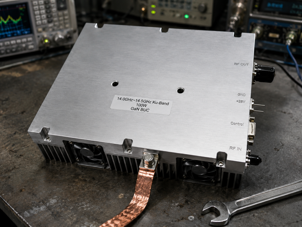
Let’s dig a little deeper. The CRF-BUC-Ku-100W features a dense, heavy-duty aluminum mechanical outline. Total package size measures 225 × 151 × 141 mm. This compact but massive unit weighs 5.5 kg. We utilize heavy finned heat sinks paired with active air cooling fans. The mechanical drawing illustrates precise mounting hole locations ensuring solid structural integration. Output power routes through a standard WR75 waveguide flange. This waveguide provides excellent high-power handling while isolating internal electronics from external cable stresses.
Mechanical Specifications
| Feature | Dimension / Spec | Reference |
| Package Size | 225 × 151 × 141 mm | Datasheet |
| Weight | 5.5 kg | Mass |
| Output Connector | WR75 Waveguide | RF Out |
10. Practical Implementation Steps for Field Engineers
Installing high-power RF gear inside substations requires rigorous procedural discipline. Engineers must verify grounding architectures before connecting weak-current telemetry cables. Never trust existing site grounds without measuring potential differences directly using calibrated multimeters. We strongly recommend installing thick braided grounding straps directly between the BUC chassis and primary earth bus bars.
Bottom line? You must eliminate parasitic current paths deliberately. Measure RF cables for common-mode currents during test transmission cycles. Utilize isolated VNA equipment for verifying antenna VSWR characteristics safely. The CRF-BUC-Ku-100W provides a robust foundation for vehicle, maritime, or ground VSAT station applications. Our factory supports custom RF/IF frequency adjustments and specific control interface options upon request. We hold ISO 9001 and GJB 9001C certifications ensuring strict manufacturing quality. System integrators can request specific test data and pattern files for detailed project review.
Compliance and Application Data
| Category | Details |
| Applications | Ground VSAT station, Maritime |
| Quality Standard | ISO 9001, GJB 9001C |
| Customization | Power supply, IF frequency |
Engineers demanding reliable communication uplinks inside high-voltage substations must address grounding physics directly. CorelixRF delivers the CRF-BUC-Ku-100W architecture specifically engineered resisting transient ground loops and false telemetry triggers. Contact our technical team for detailed integration support regarding your next critical infrastructure project.
FAQ
Q1: What is the recommended operating temperature range for the BUC? The CRF-BUC-Ku-100W operates reliably between -40 °C and 60 °C. This wide thermal tolerance suits harsh outdoor substation environments perfectly.
Q2: How does the communication interface handle interference? We implement an aviation-grade RJ45 connector. This robust interface protects weak-current Ethernet monitoring pins from physical damage and electrical ground loops.
Q3: What power supply voltage does the system require? The unit requires a 48 V DC supply, accepting a range from 36 to 72 V. We also offer an AC220V ±15% optional configuration.
Q4: Does the amplifier include built-in protection mechanisms? Yes. The architecture includes integrated receive rejection filtering, a built-in high-power isolator, and alarm/protection functions for temperature and current monitoring.
Q5: What are the physical dimensions and weight of the module? The complete package size measures 225 × 151 × 141 mm. The total weight equals 5.5 kg.
Treat substation isolation as RF and signal integrity work
Substation monitoring issues often combine grounding, Ethernet isolation, RF cable routing, amplifier margin and signal source stability. Put those details into the RFQ so the review covers the whole front-end instead of one connector.
Recommended next step: send the operating band, output power target, duty cycle, load condition, control interface, grounding or thermal limits and required FAT documents. CorelixRF can review this substation monitoring Ethernet pin isolation requirement against standard RF amplifier platforms, RF front-end options and controlled customization paths.