
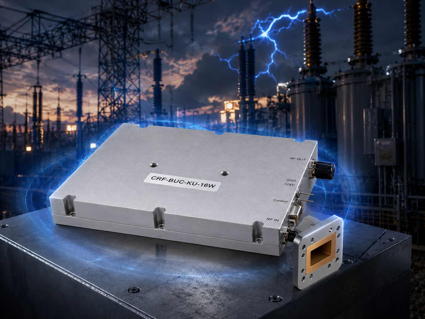
Substation monitoring systems face brutal electromagnetic interference from switching transients daily. System integrators often watch VSAT screens freeze mid-transmission inexplicably. High-current returns flood poorly designed grounding networks rapidly during electrical faults. These rogue currents seek paths through weak-current control pins constantly. Logic boards register false triggers immediately upon receiving noise spikes. CorelixRF spent twenty years diagnosing hardware failures beside massive transformers. We provide actual engineering truth rather than generic marketing promises. A ruggedized front-end demands specific physical architecture preventing current leakage. CRF-BUC-Ku-16W blocks these exact failure modes mathematically and structurally. Your Ku-band uplink requires zero downtime reporting grid anomalies instantly. Ground potential rise cannot crash a properly built Block Upconverter. Our datasheet confirms 42 dBm saturated output power continuously. Harsh environments expose weak electrical designs instantly without mercy. Let us examine physical matching logic mechanics preventing system shutdowns.
1. What Triggers System Failures During High-Voltage Transients?
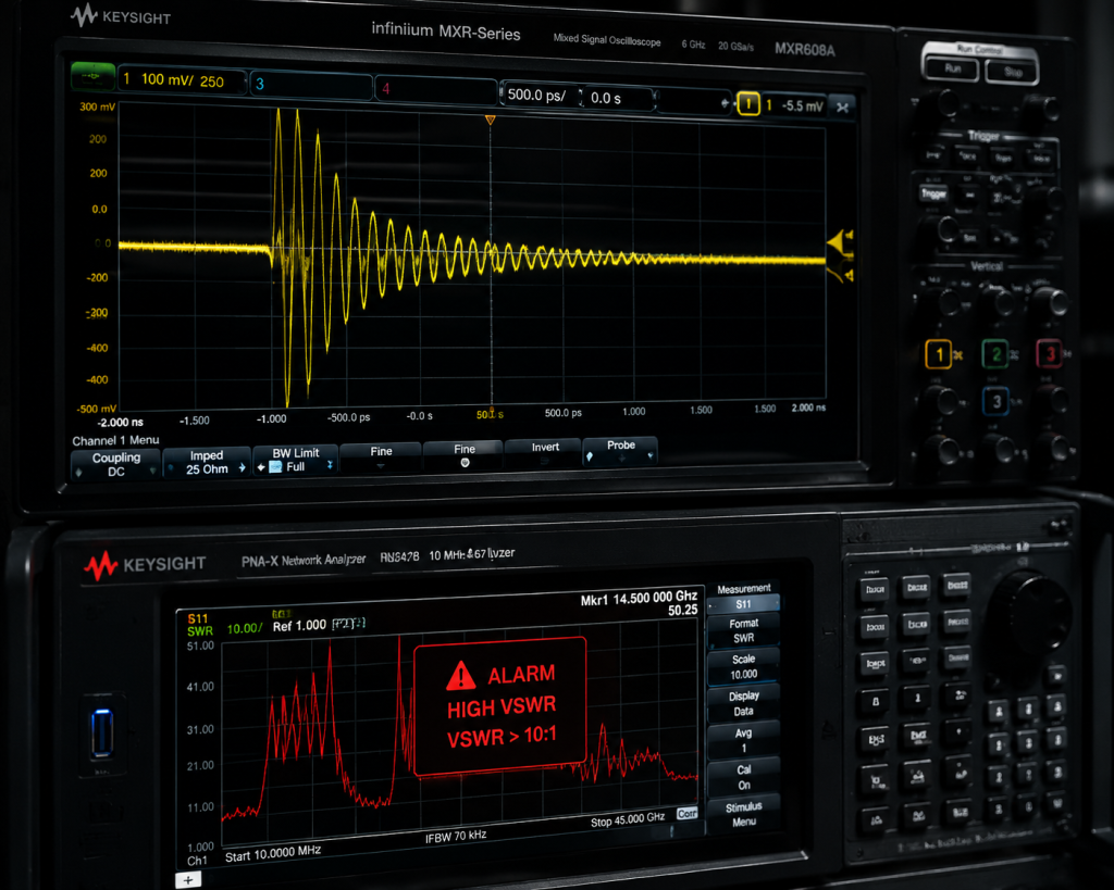
Here is the deal. A 500kV breaker throws an arc across switchgear contacts violently. Massive transient magnetic fields induce extreme voltages across nearby copper cables. Substation communication racks sit amidst this chaotic energy storm constantly. Ground potential rises violently during grid fault conditions unexpectedly. Engineers expect a stable 0V reference point across their chassis. Instead, local ground spikes reach hundreds of volts instantly. Commercial off-the-shelf transmitters fail under such abusive conditions repeatedly. Their internal logic thresholds cannot handle fluctuating reference planes properly. A micro-controller reading RS485 data suddenly sees a 5V differential spike. Equipment resets happen immediately dropping critical telemetry packets fast. You lose visibility when grid operators need data most urgently. We measure these spikes using high-speed oscilloscopes onsite regularly. The trace shows chaotic high-frequency ringing on control lines distinctly. Physics dictates that energy must find a return path always. It always takes paths presenting minimum electrical impedance. A FieldFox Vector Network Analyzer connected during switching events displays severe trace collapse. S11 reflection coefficients jump unexpectedly triggering high VSWR alarms falsely. Your monitoring network goes dark exactly when disaster strikes.
| Transient Source | Induced Voltage Spike | RF Front-End Impact | Mitigation Strategy |
| 500kV Breaker Arc | > 200V peak | RS485 logic reset | Galvanic isolation |
| Ground Fault | > 500V shift | Power supply shutdown | Wide input range DC |
| Lightning Strike | > 1000V surge | Component catastrophic failure | TVS diode arrays |
2. How Does Poor Grounding Create RF Front-End Blind Spots?
What is the real story? Many system integrators rely upon single-point chassis grounds improperly. They bolt an amplifier chassis directly against a metal mounting pole. RF grounds and DC grounds mix without proper isolation networks. High-current returns from neighboring industrial machinery flow across this shared metal path. A spectrum analyzer connected near such setups reveals terrifying noise floors. The baseline jumps erratically during heavy machinery startup sequences nearby. Your weak-current pins absorb a fraction of that return energy. Ground loops act like parasitic antennas capturing stray magnetic flux. A poorly grounded system converts environmental noise into differential voltage signals. Transmitters interpret these noise voltages as legitimate control commands randomly. Mute pins trigger active states without software instruction shutting down carriers. Transmit power drops unexpectedly causing massive packet loss immediately. Engineering teams spend weeks chasing phantom software bugs blindly. They ignore physical layer grounding realities designing their integration cabinets. An unbalanced ground grid acts like an injection probe driving interference inward. Our field engineers measure massive common-mode currents riding outer cable shields. We calculate exact noise figures based upon these stray currents mathematically.
| Grounding Topology | Return Current Path | Signal Interference Risk | BUC Operation Status |
| Shared Chassis Metal | Random parasitic loops | Severe phase noise jump | Unstable gain steps |
| Isolated DC/RF Ground | Defined cable shields | Minimal logic threshold shift | Stable 42 dBm output |
| Floating System | Capacitive coupling | High static buildup | Component degradation |
3. Why Do Weak-Current Pins Suffer From High-Current Returns?
This is where it gets interesting. Look closely at standard interface designs inside basic upconverters. Weak-current logic operates on 3.3V or 5V thresholds typically. High-current power rails drive 80W loads toward radio frequency generation. A loose grounding lug forces 5A DC currents backward through delicate data cables. Ethernet cables lacking shielded twisted pairs become sacrificial return paths quickly. CorelixRF engineers dissect failed units from competitor installations routinely. We find scorched logic board traces near communication headers frequently. The physics remain unforgiving regarding current loops crossing dissimilar boundaries. A logic pin designed for milliampere signaling cannot survive ampere-level surges. High-current returns alter local voltage potentials across micro-controller inputs drastically. Thresholds cross from logical zero toward logical one erroneously. This misinterpretation commands a Block Upconverter off state unexpectedly. Telemetry stops broadcasting immediately leaving control rooms blind completely. Proper matching logic requires massive physical impedance barriers against rogue currents. We calculate printed circuit board trace widths surviving short-circuit fault conditions. Dielectric breakdown voltages must exceed highest expected ground potential differences easily.
Component Level Failure Mechanisms
Micro-controllers latch up permanently when input pins exceed supply voltages momentarily. P-N junctions inside silicon devices avalanche uncontrollably under reverse bias conditions. We replace standard transceivers utilizing highly ruggedized industrial components exclusively.
| Pin Designation | Normal Current | Fault Return Current | Physical Damage Result |
| RS485 Data+ | < 50 mA | > 1.5 A | Transceiver IC failure |
| Mute Control | < 10 mA | > 1.0 A | False state toggling |
| Ethernet TX/RX | < 20 mA | > 2.0 A | Magnetics transformer burnout |
4. What Are The Substation VSAT Communication Link Constraints?
You might be wondering. Why select Ku-band frequencies for power grid telemetry networks? C-band antennas require massive physical footprints unsuited for crowded substation yards. Ka-band links suffer heavy rain fade during severe weather events predictably. A Ku-band system operating between 13.75 and 14.5 GHz strikes a balance perfectly. It pushes high data rates while maintaining reasonable dish sizes physically. However, these higher frequencies demand extreme phase noise purity from local oscillators. Our CRF-BUC-Ku-16W delivers phase noise below -73 dBc/Hz at 1 kHz offset. A vibrating 50Hz power transformer physically shakes equipment racks violently. Microphonic effects degrade poorly constructed dielectric resonators rapidly under stress. The communication link budget tightens considerably under such environmental abuse. We maintain a ±1.5 dB gain flatness across a 500 MHz bandwidth. System integrators need 16W saturated power just penetrating typical rain attenuation layers. We guarantee 42 dBm output power strictly preventing signal dropouts. Substation control centers require constant 64 QAM modulation schemes functioning flawlessly. Dense modulation fails instantly if phase noise smears constellation points randomly.
Spectral Purity Requirements
Radar and VSAT engineers measure adjacent channel leakage ratios strictly. A transmitter generating false spurs ruins network capacity for neighboring terminals. We maintain spurious emissions strictly below -55 dBc mathematically.
| Phase Noise Offset | Maximum Specified Level | Modulation Impact |
| @ 100 Hz | -63 dBc/Hz | Slow carrier tracking errors |
| @ 1 kHz | -73 dBc/Hz | Constellation rotation |
| @ 10 kHz | -83 dBc/Hz | Symbol decoding failure |
5. How Do We Design A Robust Matching Logic For Interference?
Now consider this fact. Hardware matching logic requires more than basic impedance tuning physically. We build deliberate isolation barriers between high-power RF modules and sensitive digital controllers. CorelixRF utilizes military-grade optocouplers buffering every incoming RS485 signal line physically. Photons transfer data across physical gaps without conducting stray electrical currents. We define this physical gap as an absolute firewall against substation noise. A high-current return cannot jump an optical isolation barrier ever. Furthermore, we implement rigorous RF decoupling capacitors along every power trace. These capacitors shunt high-frequency electromagnetic interference directly toward chassis ground harmlessly. A 10 MHz reference signal enters via IF ports carrying 0 dBm power. Our internal phase-locked loop rejects external voltage spikes riding alongside that reference. We maintain a stable 12.8 GHz local oscillator frequency flawlessly. Logic boards remain calm despite surrounding electrical chaos destroying nearby equipment. This approach solves false trigger anomalies permanently eliminating frantic troubleshooting calls. Common mode chokes suppress differential noise keeping ethernet packets intact perfectly.
Circuit Board Trace Routing
We separate digital grounds away from high-power amplifier grounds physically. Multilayer boards utilize dedicated buried ground planes sinking thermal and electrical loads.
| Logic Protection Component | Engineering Purpose | Substation Fault Response |
| High-Speed Optocoupler | Block galvanic current paths | Maintains data integrity |
| Low-ESR Decoupling Caps | Shunt RF noise toward ground | Flattens voltage ripple |
| Common Mode Choke | Reject simultaneous cable noise | Preserves RS485 differential |
6. What Makes GaN Amplification Resilient In High-Noise Zones?
Ready for the good part? Gallium Nitride technology fundamentally changes microwave engineering rules completely. Legacy Gallium Arsenide chips suffer severe breakdown risks under fluctuating supply voltages. GaN transistors operate effortlessly at higher drain voltages naturally. A substation transient might sag DC supplies momentarily dropping line voltages. GaN handles these thermal and electrical shocks significantly better than older semiconductors. Our CRF-BUC-Ku-16W employs high-efficiency GaN devices delivering 65 dB small signal gain. It dissipates 80W typical power consumption via heavy aluminum heat sinks. An IP65 rated enclosure protects these transistors from conductive dust particles. Salty coastal substation environments corrode exposed circuitry rapidly causing massive failures. We seal our RF cavities tightly preventing moisture ingress completely. GaN devices offer superior third-order intermodulation performance during multi-carrier transmissions. We specify IM3 levels below -25 dBc at 3 dB back-off explicitly. A clean spectrum prevents adjacent channel interference thoroughly maintaining network integrity. Heat dissipation remains critical when ambient temperatures hit 60 degrees Celsius outside. Deep cooling fins channel airflow pulling thermal energy away from semiconductor junctions.
| Semiconductor Material | Breakdown Voltage | Thermal Conductivity | RF Output Capability |
| Legacy GaAs | Low (< 15V) | Poor | Limited saturated power |
| High-Efficiency GaN | High (> 40V) | Excellent | 42 dBm continuous |
7. How Does CRF-BUC-Ku-16W Mitigate EMI And False Triggers?
The truth is simple. CorelixRF designs focus relentlessly upon physical construction integrity absolutely. Look at a mechanical outline drawing provided within our datasheet closely. A solid milled aluminum block houses delicate RF routing channels securely. This solid metal shell acts as a perfect Faraday cage against 500kV transients. We terminate input signals using N-Female connectors featuring robust threaded shielding. Output signals exit via WR75 waveguide flanges demanding precise mechanical mating. Waveguides naturally reject low-frequency electrical noise filtering out grid hum completely. The internal architecture separates power conditioning zones from RF amplification stages strictly. False triggers require a noise voltage exceeding logic high thresholds forcefully. We elevate those thresholds while clamping transient spikes aggressively using hardware limiters. A technician carrying a spectrum analyzer measures no spurious emissions exceeding -55 dBc. We eliminate source noise mathematically and structurally securing transmission purity. Your monitoring network stays active indefinitely broadcasting telemetry without dropping packets. A 1 kg package size dictates dense internal layouts avoiding capacitive coupling risks.
Output Port Reflection Handling
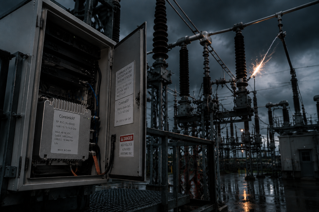
Substation antennas accumulate ice causing high VSWR conditions abruptly. Our isolators protect internal GaN stages against 2:1 output mismatch reflections safely.
| Specification Category | Parameter Value | Environmental Benefit |
| Housing Material | Milled Aluminum | Blocks stray magnetic fields |
| Input Connector | N-F Threaded | Prevents vibration disconnects |
| Output Connector | WR75 Waveguide | High pass filter mechanics |
8. Why Does A Wide Supply Voltage Range Prevent Logic Resets?
But here is the kicker. Power grids suffer severe brownouts during short circuit events routinely. A standard 24V supply might drop toward 18V suddenly under heavy load. Narrow-band power modules reset instantly under such extreme load droop conditions. Their micro-controllers reboot, dropping communication links for several minutes disastrously. CorelixRF built a custom power conditioning module absorbing extreme voltage swings naturally. The CRF-BUC-Ku-16W accepts any supply voltage spanning 18 volts toward 55 volts. It operates perfectly on 24V, 28V, or 48V substation battery banks seamlessly. An internal buck-boost converter stabilizes transistor drain voltages regardless of external fluctuations. We measured continuous 42 dBm output power while sweeping input voltage drastically. This wide acceptance range acts like an electrical shock absorber internally. High-current return paths cannot drag local rails low enough causing logic faults. Your transmission continues broadcasting sensor data uninterrupted providing grid operators crucial visibility. Regulating internal rails prevents phase pushing anomalies associated with poor power supplies.
| Input DC Voltage | Internal Drain Voltage | RF Output Power | Link Status |
| 48V Nominal | 28V Regulated | 42 dBm | Locked / Transmitting |
| 24V Nominal | 28V Regulated | 42 dBm | Locked / Transmitting |
| 18V Brownout | 28V Regulated | 42 dBm | Locked / Transmitting |
9. How Do PT02E Connectors Block Stray Ground Currents?
It boils down to this. Consumer grade ethernet jacks fail within industrial substations predictably quickly. Plastic RJ45 connectors provide zero electromagnetic shielding against intense magnetic fields. We specify rugged PT02E-14-12 aviation connectors handling power and communications simultaneously. These circular metal connectors feature threaded locking rings preventing vibration-induced disconnections. A heavy metal shell couples cable shielding directly against our amplifier chassis securely. Stray ground currents travel along outer cable braids dumping safely into earth ground. Internal weak-current pins remain protected inside thick dielectric inserts physically. RS485 telemetry and Ethernet packets cross this interface devoid of common-mode noise. A dense pin arrangement requires meticulous wiring techniques preventing cross-talk completely. We maintain absolute separation between 48V DC lines and low-voltage monitoring signals. Quality interface hardware stops interference before entering sensitive RF cavities destroying chips. Our production technicians verify shield continuity using low resistance milli-ohm meters strictly. An exposed wire acts like an antenna capturing every switching transient nearby. We encapsulate connections blocking environmental degradation permanently.
Vibration Resistance Standards
Transformers buzz continuously generating low frequency mechanical waves degrading solder joints. Threaded aviation connectors grip mating surfaces tightly defeating persistent mechanical loosening.
| Connector Attribute | Physical Feature | Interference Defeat Mechanism |
| Metal Shell | Conductive Aluminum | Shunts common mode noise |
| Threaded Coupling | Screw Lock | Prevents ground separation |
| Dielectric Core | High-Temp Polymer | Isolates high voltage potentials |
10. What Is The Final Integration Blueprint For Substation RF?
The bottom line is clear. System integrators cannot rely upon luck during substation deployments ever. Engineering truth requires addressing ground potential anomalies through physical hardware isolation. High-current returns will destroy weak-current pins without proper architectural matching logic. CorelixRF spent twenty years perfecting high-power microwave transmitters surviving harsh electrical abuse. We deliver 16W Ku-band energy pushing data through heavy rain effectively. Your telemetry networks demand absolute hardware reliability avoiding false logic triggers entirely. Stop wasting weeks troubleshooting phantom software glitches caused by poor grounding loops. We invite engineers testing our equipment alongside their hardest spectrum analyzer setups. Analyze our -150 dBm/Hz receive in-band noise floor independently verifying performance claims. Our datasheet specifies exact parameters guaranteeing successful VSAT base station integration. Contact our engineering team discussing your specific link budget requirements soon. A solid mechanical foundation dictates long term microwave transmission success undeniably.
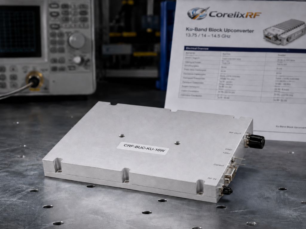
We summarized physical mechanisms behind false logic triggers affecting substation VSAT links deeply. Stray high-current returns devastate poorly grounded weak-current control pins regularly under fault conditions. CorelixRF developed ruggedized isolation architecture blocking these electrical anomalies physically preventing downtime. Deploying CRF-BUC-Ku-16W transmitters guarantees continuous 42 dBm telemetry uplinks regardless of interference. Engineers should integrate isolated RF hardware solving grid communication failures permanently starting today.
FAQ
Q1: What causes false triggers on RS485 pins inside substations?
High-current returns from grid faults flow through weak-current grounds, shifting logic thresholds erroneously across micro-controller input buffers.
Q2: How does an optocoupler block ground loops physically?
It converts electrical signals into light pulses internally, transferring data across a physical gap without continuous conductive metal paths.
Q3: Why select a Ku-band BUC for power grid monitoring networks?
Ku-band balances high data throughput requirements against manageable physical antenna dish sizes suitable for crowded industrial transformer yards.
Q4: Does supply voltage fluctuation affect GaN amplifier output power?
Our internal wide-range DC converter maintains stable transistor bias continuously, preventing transmit power drops during sudden grid brownouts.
Q5: Can a PT02E connector survive high vibration environments reliably?
Yes, military-grade threaded locking mechanisms prevent contact separation forcefully and maintain solid shield grounding against the chassis continuously.
Translate rugged-site symptoms into a complete RF-chain review
Rugged RF issues often combine grounding, vibration, thermal range, connector retention, signal source stability and amplifier power margin. Share the site condition and acceptance evidence needed before choosing a platform.
Recommended next step: send the operating band, output power target, duty cycle, load condition, control interface, protection or thermal limits and required FAT documents. CorelixRF can review this How to Prevent False Triggers in Substation RF Front-End Designs? requirement against standard RF amplifier platforms, RF front-end options and controlled customization paths.