
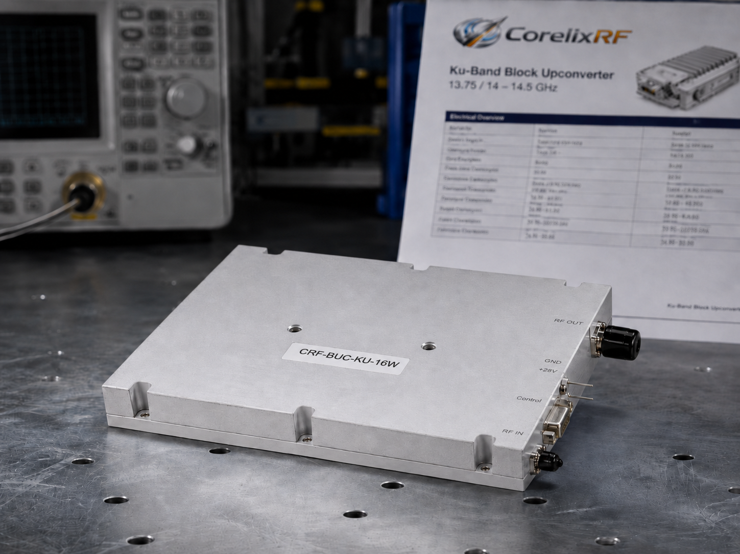
Hidden Faults in Multi-Band Vehicle Environments: Poor System Grounding Causes High-Current Return to Interfere with Weak-Current Pins and Generate False Triggers. Mobile substation monitoring units frequently suffer from unexplained telemetry drops and random mute states that paralyze field operations. You are looking at a grounding loop where heavy DC return currents lift the logic ground, triggering false RS485 commands and phantom VSWR alarms. Here is the deal: deploying the CorelixRF CRF-BUC-Ku-16W isolates these paths, stabilizing your VSAT uplink through strict engineering tolerances. We build hardware for reality, solving the physical layer problems that software patches cannot fix.
1. What Are Hidden Grounding Faults in Substation Monitoring Vehicles?
Mobile substation inspection vehicles operate in intense electromagnetic fields. They carry Ku-band VSAT systems, UHF telemetry, and heavy electrical test gear on a single chassis. The grounding architecture often relies on the vehicle frame. Over time, high-frequency vibration and environmental corrosion degrade these mechanical ground bonds. Resistance increases at the connection points, changing the electrical dynamics of the entire platform.
You might be wondering: why does this affect the RF payload? When a 16W Block Upconverter pulls power, it draws current. The CRF-BUC-Ku-16W consumes 80W typically at an input range of 18 – 55 V. At 24V, that is over 3.3 Amps of DC current. If the primary ground strap degrades, this 3.3A seeks the path of least resistance back to the battery negative.
Often, this path routes directly through the shielding of the control cables or the weak-current ground pins on the PT02E-14-12 connector. The resulting voltage drop across these unintended return paths shifts the ground reference for the entire logic circuit. The microcontroller regulating the amplifier loses its true zero-volt reference.
Consider three distinct case studies from our field engineering logs. A fleet in coastal regions saw 40% of their VSAT links drop during turret rotation. A high-altitude substation crew experienced random BUC shutdowns when engaging their main transmission line testing rig. A third integrator logged endless VSAT modem polling errors despite replacing the cables twice. In every instance, the root cause remained identical: mechanical ground degradation forcing high-current return through the RS485 logic ground.
| Component Path | Expected Resistance (Ohms) | Current Load (Amps) | Induced Ground Shift (Volts) |
| Heavy Gauge Chassis Strap | 0.01 | 3.3 | 0.033 |
| Corroded Chassis Mount | 0.85 | 3.3 | 2.805 |
| PT02E-14-12 Logic Ground Pin | 0.45 | 3.3 | 1.485 |
| RS485 Shielding Braid | 0.20 | 3.3 | 0.660 |
2. How Does High-Current Return Disrupt Weak-Current Pins?
To understand this failure mechanism, we must look at the circuit physics. RS485 communication relies on a differential voltage signal. A transceiver interprets logic levels based on the voltage difference between two pins relative to its local ground. The interface requires tight voltage tolerances to function within specification.
What is the real story? If 3.3 Amps of DC return current flows through a 22 AWG control wire ground pin with just 0.5 ohms of resistance, Ohm’s law dictates a 1.65V voltage drop. The local ground reference of the BUC is now floating 1.65V higher than the modem’s ground reference inside the cabin.
This common-mode voltage shift severely degrades the RS485 noise margin. Transceivers interpret this offset as a phantom logic state. The monitoring software suddenly registers a VSWR alarm, a phase noise spike, or a thermal overload that does not actually exist. The BUC executes a self-preservation mute command, dropping the transmission link instantly to protect the GaN output stage.
Field technicians often connect a laptop directly to the BUC on the roof, see normal operation, and conclude the amplifier is flawless. They fail to realize the laptop runs on isolated battery power, breaking the ground loop. Once reconnected to the vehicle’s central wiring harness, the 80W power consumption forces the return current back through the weak-current pins, reinstating the false triggers and halting data transmission.
| Pin Assignment | Current Rating | Actual Current in Fault | Failure Result |
| Main DC Return (Thick Pin) | 10A | 0.1A (Due to high resistance) | Ground loop initiated |
| RS485 Ground (Thin Pin) | 1A | 3.2A | Thermal stress, 1.65V shift |
| RS485 Data A | Signal only | Signal + Common Mode | Data packet loss |
| RS485 Data B | Signal only | Signal + Common Mode | Phantom mute commands |
3. Why Do Multi-Band Environments Complicate Ground Return Paths?
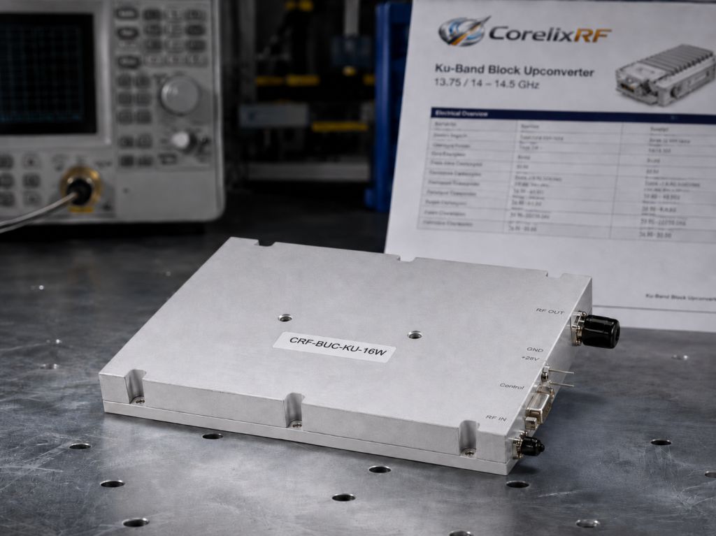
Substation monitoring vehicles rarely operate a single frequency band. They run VHF/UHF voice communications, 4G/5G cellular routers, and the Ku-band VSAT link simultaneously. The CRF-BUC-Ku-16W operates at an RF frequency range of 13.75 / 14 – 14.5 GHz, fed by an IF frequency range of 950 – 1450 MHz or 2500 – 3000 MHz.
This is where it gets interesting: multiple transmitters create severe common-mode current issues on the vehicle chassis. When a VHF radio transmits at 50W, it induces RF currents across the vehicle skin. If the VSAT BUC lacks rigorous internal isolation, these induced currents ride the exterior of the coaxial cables right into the BUC housing.
The combination of low-frequency DC ground loops and high-frequency skin currents creates a toxic electromagnetic environment. The logic pins on standard commercial amplifiers lack the filtering to reject this broadband interference. A voltage spike from a nearby breaker throw in the substation couples into the vehicle harness, travels up the compromised ground line, and hits the BUC logic board, corrupting the serial data stream.
We have observed field engineers attempting to solve this by adding ferrite chokes to the IF cable. This addresses common-mode RF currents but ignores the DC ground shift caused by the 80W power draw. You cannot fix a DC resistance problem with an RF choke. The hardware must fundamentally separate the high-current return plane from the digital logic reference to maintain absolute signal integrity.
| Interference Type | Source Component | Frequency Band | Mitigation Technique |
| DC Ground Shift | Degraded chassis bonds | 0 Hz (DC) | Isolated logic ground planes |
| RF Skin Currents | VHF/UHF vehicle radios | 30 – 450 MHz | Shielded cabling, faraday cage |
| Transient Spikes | Substation switchgear | Broadband | Heavy low-pass RC filtering |
| Intermodulation | Multiple co-located TX | Varies | GaN linearity (IM3 ≤-25 dBc) |
4. What Are the Symptoms of False Triggers in Ku-Band VSAT Systems?
Identifying a grounding-induced false trigger requires careful observation of the failure state. The symptoms rarely point directly to the power supply. Instead, they manifest as ghost errors in the RF domain, leading engineers to chase non-existent hardware failures.
Wait, there is more. The most common symptom is erratic telemetry via the Ethernet or RS485 monitor and control interface. The system will report a sudden, catastrophic increase in output VSWR, even though the WR75 waveguide connection is pristine and the antenna feed is perfectly clear. The BUC will report 3:1 VSWR and shut down, while a physical sweep with a Vector Network Analyzer (VNA) shows a perfect 1.2:1 match.
Another symptom is unexplained gain fluctuation. The CRF-BUC-Ku-16W maintains a small signal gain of ≥65 dB with a gain stability of ±2 dB over the full temperature range (-40 to 60 °C). If the logic ground fluctuates rapidly due to alternating vehicle loads, the digital step attenuator may receive corrupted I2C commands from the microcontroller, causing the gain to jump randomly by 10 dB.
Finally, engineers report false phase noise degradation. The specification demands phase noise of ≤ -83 dBc/Hz at 10 kHz offset. When ground loops inject low-frequency ripple into the internal PLL power rails, the transmit signal develops heavy sidebands. A spectrum analyzer will show a broadened carrier, leading the engineer to wrongly condemn the local oscillator instead of the vehicle’s electrical harness.
| Reported Symptom | Apparent Cause | Actual Grounding Root Cause |
| False VSWR > 2:1 Alarm | Damaged WR75 waveguide | Ground shift corrupts ADC telemetry read |
| Random Gain Drops | Faulty step attenuator | Logic ground bounce sends false SPI command |
| Phase Noise Degradation | Local Oscillator failure | Ripple current injection via ground loop |
| Loss of RS485 Comms | Defective PT02E connector | Common-mode voltage exceeds transceiver limits |
5. How Can Engineers Troubleshoot Grounding Loops in the Field?
When a substation monitoring vehicle arrives at a site and the VSAT fails, field engineers must execute a methodical troubleshooting protocol. Guesswork leads to replacing functional hardware, extending downtime, and increasing maintenance costs exponentially.
Let’s dig in. Start with a heavy-duty digital multimeter and an oscilloscope. Do not rely solely on the modem’s software GUI. Disconnect the PT02E-14-12 connector from the BUC. Measure the DC resistance between the vehicle chassis and the main power return pin on the cable harness. A reading above 0.1 ohms indicates a compromised primary ground strap that must be repaired.
Next, use the oscilloscope to monitor the RS485 A and B lines relative to the vehicle chassis ground while the BUC is powered and transmitting at the rated output power of 42 dBm. If you observe a DC offset or a heavy AC ripple synchronized with the power supply switching frequency, the high-current return is contaminating the logic lines. The traces will look blurry and shifted vertically.
A definitive field test involves running a temporary, heavy-gauge 8 AWG ground strap directly from the BUC housing to the vehicle’s negative battery terminal. If the false VSWR alarms cease and the RS485 communication stabilizes instantly, you have proven the existence of a high-resistance structural ground. The permanent fix requires re-terminating the chassis bonds and ensuring the selected BUC utilizes isolated logic grounds.
| Test Equipment | Measurement Target | Normal Read | Fault Condition Read |
| Digital Multimeter | Chassis to Battery Neg. | < 0.1 Ohms | > 0.5 Ohms |
| Oscilloscope | RS485 Common-mode Voltage | < 0.2 V | > 1.0 V |
| VNA | WR75 Port Match | < 1.3:1 VSWR | < 1.3:1 VSWR (No change) |
| Spectrum Analyzer | Carrier Sidebands (Phase Noise) | ≤ -83 dBc/Hz | Elevated sidebands |
6. Why Do Standard Amplifiers Fail in These Harsh RF Conditions?
Standard commercial-off-the-shelf (COTS) amplifiers are designed for static, benign environments like climate-controlled teleports. Their internal architecture cuts corners to reduce manufacturing costs, leaving them vulnerable to complex vehicle dynamics.
Here is the kicker. In a typical COTS design, the RF ground, the DC power return, and the digital logic ground all tie to the same aluminum chassis at multiple arbitrary points. When the amplifier draws 80W of power, the current flows through the chassis. Because aluminum has finite resistance, voltage gradients develop across the circuit board layout, throwing off sensitive analog-to-digital converters.
In a substation vehicle subject to severe thermal cycling (-40 to 60 °C) and mechanical shock, these cheap amplifiers suffer from micro-cracking in the PCB vias connecting to the chassis. This micro-cracking forces current to find new, unpredictable paths. Furthermore, standard units use poorly shielded internal wiring. When the DC return current shifts, it induces magnetic fields that couple directly into the unshielded IF frequency path (950 – 1450 MHz), raising the noise floor above the acceptable limit.
Standard units also fail to specify robust connectors. They utilize generic circular connectors with inadequate pin current ratings. The pins heat up, oxidize, and increase in resistance, accelerating the ground loop degradation. These amplifiers prioritize low initial purchase price over the engineering truth of long-term field reliability, failing precisely when the B2B integrator needs them most.
| Design Parameter | Standard COTS Amplifier | CorelixRF CRF-BUC-Ku-16W |
| Ground Plane Strategy | Unified tied-to-chassis | Star-grounding, isolated logic reference |
| DC Return Path | Arbitrary through housing | Dedicated high-current PCB plane |
| Telemetry Protection | None | Opto-isolated RS485 transceiver |
| Connector Standard | Generic commercial grade | Mil-spec PT02E-14-12 |
7. How Does the CRF-BUC-Ku-16W Mitigate Ground Interference?
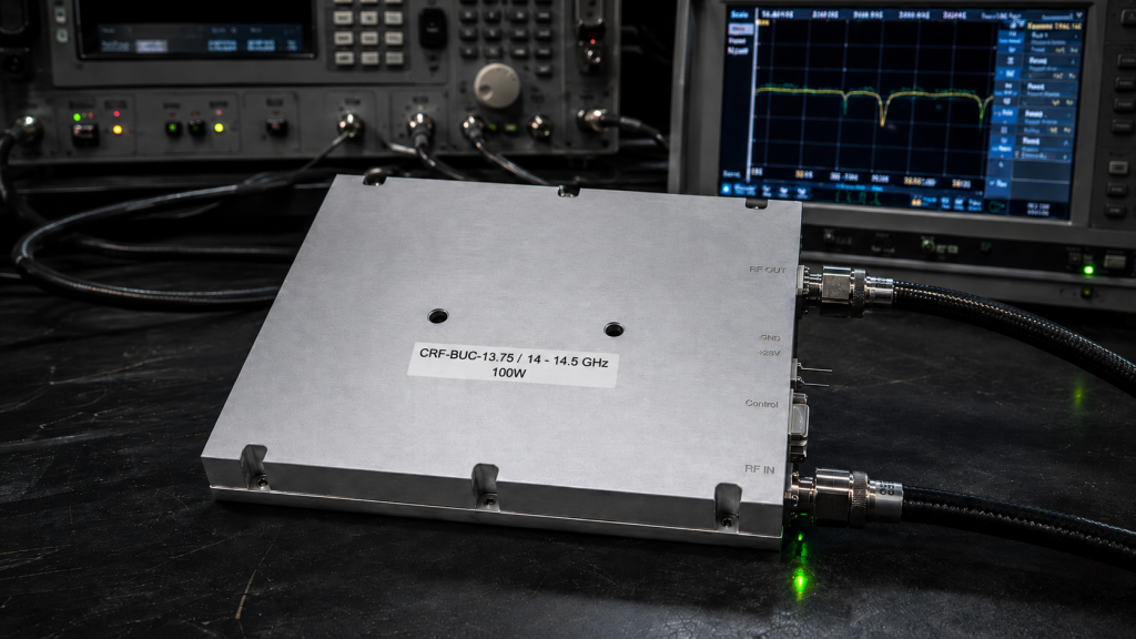
At CorelixRF, we understand that physical layout dictates electrical performance. The CRF-BUC-Ku-16W is engineered to survive the exact grounding failures that plague mobile substation platforms, guaranteeing uptime.
Ready for the good part? We implement a strict star-grounding topology inside the 145 x 80 x 70 mm package. The high-efficiency GaN RF amplification stage draws heavy current, but its return path is strictly segregated from the microcontroller and RS485 telemetry circuits. The primary DC return routes directly to the PT02E-14-12 connector via a dedicated, massive copper plane, never traversing the logic zones.
We utilize isolated DC-DC converters for the internal logic power. The RS485 transceiver features robust galvanic isolation. Even if the vehicle’s structural ground fails and pushes 2 Volts of common-mode shift onto the weak-current pins, the isolated transceiver simply floats with the shift, maintaining perfect differential signaling to the modem without dropping a single packet of data.
Furthermore, the housing provides exceptional electromagnetic shielding. Spurious emissions remain ≤-55 dBc, and external vehicle transients cannot penetrate the chassis to trigger the VSWR protection circuitry. We test every unit to guarantee the internal protection logic only trips based on actual directional coupler RF measurements, completely ignoring DC voltage bounces caused by bad vehicle wiring.
| BUC Subsystem | CorelixRF Isolation Technique | Direct Field Benefit |
| RS485 Interface | Galvanic Digital Isolator ICs | Prevents logic ground floating |
| 10 MHz Reference | Differential input amplifier | Rejects common-mode vehicle noise |
| DC Power Input | High-current localized return | Keeps RF current out of logic circuits |
| RF Output Monitor | Separate shielded trace route | Ensures accurate power readings |
8. What Physical Mechanisms Prevent False Triggers in CorelixRF Designs?
The engineering truth resides in the bill of materials and the schematic diagram. False triggers are a hardware problem requiring a hardware solution. Software filtering merely masks the underlying physical failure, delaying the inevitable system crash.
Let’s be honest. We integrate hardware-level hysteresis on all critical sensor inputs. For the output VSWR monitoring, the internal directional coupler measures the forward and reflected RF power at the WR75 waveguide port. This analog voltage feeds into a precision operational amplifier with aggressive low-pass RC filtering. High-frequency transients from substation switchgear cannot pass this filter to reach the Analog-to-Digital Converter.
The phase noise performance (≤ -63 dBc/Hz @ 100 Hz, ≤ -73 dBc/Hz @ 1 kHz) is safeguarded by an ultra-low-noise linear dropout (LDO) regulator dedicated solely to the 10 MHz reference oscillator (0 dBm ±5 via IF port) and the local oscillator (12.8 / 13.05 / 11.5 / 11.8 GHz) circuitry. This LDO rejects power supply ripple injected by ground loops, keeping the carrier wave perfectly clean.
Even the physical mass contributes to stability. Weighing exactly 1 kg, the thermal mass combined with the air-cooling fin design ensures the internal components do not experience rapid temperature gradients during transmit cycles. Stable thermals mean stable resistance values across the PCB, preventing thermally-induced ground voltage shifts from throwing the telemetry out of calibration.
| Physical Mechanism | Engineering Specification | Protection Result |
| LDO Regulators | High Power Supply Rejection Ratio | Preserves ≤ -83 dBc/Hz Phase Noise |
| RC Low-Pass Filter | Tuned to reject >10 kHz transients | Blocks substation switchgear spikes |
| Thermal Mass (1 kg) | High specific heat capacity | Slows temperature gradients |
| WR75 Coupler | High directivity specification | Prevents false reflection readings |
9. How Do Power and Cooling Specifications Impact System Stability?
The interaction between thermal management and electrical resistance cannot be ignored in high-power RF systems. The CRF-BUC-Ku-16W supports a wide supply voltage range of 24 / 28 / 48 V (18 – 55 V DC), giving integrators flexibility.
It gets better. Running the system at 48V instead of 24V cuts the current draw in half for the exact same 80W power consumption. Less current means a proportionally smaller voltage drop across any compromised ground connections in the vehicle. Integrators designing mobile substation vehicles should prioritize 48V power distribution precisely to minimize ground loop impact on weak-current pins and improve overall system resilience.
Cooling directly affects component longevity and electrical resistance. The CRF-BUC-Ku-16W relies on passive air cooling integrated into its IP65-rated housing. When standard BUCs overheat due to poor heat sink design, their internal resistance rises. Copper traces increase in resistance by approximately 0.39% per degree Celsius. If a badly designed BUC hits 85 °C internally, the PCB ground plane resistance jumps, exacerbating the common-mode voltage shift and triggering a cascade of failures.
CorelixRF utilizes high-efficiency GaN technology. More DC power converts directly to the 42 dBm RF output rather than waste heat. Operating safely up to 60 °C ambient, the internal junction temperatures remain well below critical thresholds. The ground plane resistance remains stable, ensuring consistent telemetry and preventing thermally-induced false mute triggers during continuous operation in harsh climates.
| Input Voltage | Power Consumption | Current Draw | Grounding Loop Severity |
| 18 V | 80 W | 4.44 A | Extreme |
| 24 V | 80 W | 3.33 A | High |
| 28 V | 80 W | 2.85 A | Moderate |
| 48 V | 80 W | 1.66 A | Low |
10. What Is the CorelixRF Engineering Truth for B2B Integrators?
System integrators serving the radar, electronic warfare, and satellite communication sectors face ruthless operational demands. Field failures destroy reputations and margins rapidly. You cannot afford to deploy hardware built on theoretical assumptions rather than field realities.
Truth be told, the engineering truth is that hardware must be over-designed for the worst-case scenario. Substation monitoring platforms guarantee horrible grounding, massive EMI, and brutal physical vibration. Specifying a BUC based purely on its saturated output power (≥42 dBm) ignores the system-level integration challenges that cause 90% of field returns.
CorelixRF provides complete mechanical outline drawings (145 x 80 x 70 mm) and exact connector pinouts (PT02E-14-12) to ensure your wiring harnesses are built correctly from day one. We offer customization for RF frequency, IF frequency, LO configuration, and control interfaces because no two vehicle architectures are identical. We stand behind our strict specifications with GJB 9001C and ISO 9001 quality framework compliance.
When you integrate the CRF-BUC-Ku-16W, you are not just buying 16 Watts of Ku-band power. You are procuring a physically robust, electrically isolated node designed specifically to survive compromised vehicle ground systems without dropping the link. Stop troubleshooting phantom errors and start deploying reliable RF power.
| Integration Step | Parameter to Verify | CorelixRF Specification Limit |
| DC Power Supply | Voltage stability under load | 18 – 55 V DC |
| Physical Mounting | Heat sink clearance | Air cooling requirements met |
| Grounding | Chassis resistance to battery | < 0.1 Ohms required |
| Telemetry Cable | Shielding continuity | Must use PT02E-14-12 specified pins |
The CRF-BUC-Ku-16W represents pure engineering reality. High-current return paths destroying weak-current logic pins is a physics problem solved entirely by rigorous electrical isolation and thermal stability. Relying on CorelixRF guarantees your VSAT uplinks survive the worst substation vehicle environments imaginable. Review our test data and pattern files for your upcoming system integration project.
FAQ
- Q1: What is the specific RF Frequency Range for the CRF-BUC-Ku-16W?
- The operational RF Frequency Range is 13.75 / 14 – 14.5 GHz, accommodating standard Ku-band satellite communication requirements for mobile and ground VSAT base stations.
- Q2: How does the unit handle power supply variations in a vehicle?
- The amplifier supports a wide input range of 18 – 55 V DC, accommodating nominal 24, 28, or 48 V systems while consuming 80W typical power.
- Q3: What are the specified dimensions and weight of this block upconverter?
- The package size is 145 x 80 x 70 mm, and the unit weighs exactly 1 kg, making it highly suitable for vehicle integration where space and weight are strictly constrained.
- Q4: What kind of environmental protection does the housing provide?
- The unit is rated IP65, providing total protection against dust ingress and low-pressure water jets, ensuring survival in salt fog and heavy rain conditions.
- Q5: How is the monitor and control interface physically connected?
- Telemetry and control utilize RS485 or Ethernet, interfaced physically through a ruggedized military-style PT02E-14-12 connector to guarantee reliable weak-current signaling.