
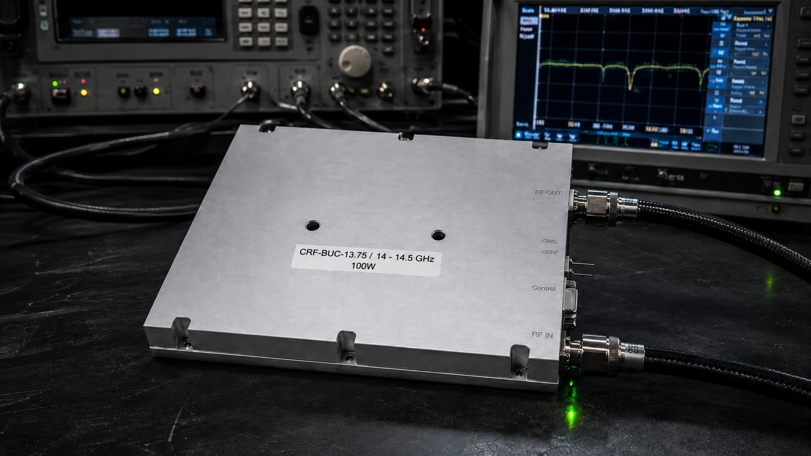
Field engineers often face incredibly frustrating random VSWR alarms or unexpected transmit power drops when deploying complex multi-band vehicle satellite communication systems. You connect an expensive oscilloscope, only finding messy noise floors overriding your critically weak control signals. We manufacture premium RF hardware directly at CorelixRF. Our thirty years of extensive factory experience analyzing these highly specific mobile platform failures reveals a consistently repeatable pattern. System poor grounding creates massive high current returns. This aggressive return current actively interferes with delicate weak monitor pins. Such interference causes immediate direct false triggers within your logic control boards. Here is the deal. You can successfully fix this recurring issue by comprehensively understanding ground loop mechanics. Selecting properly isolated hardware like our CRF-BUC-Ku-100W completely eliminates these phantom system alarms. This highly detailed engineering guide thoroughly explains exact field troubleshooting steps for mobile satellite setups.
1. What Causes Multi-Band Vehicle Signal Anomalies During Deployment?
● Identifying Ground Loop Symptoms in the Field
● How High Current Returns Behave in Mobile Platforms
You might be wondering why a perfectly bench-tested RF module suddenly fails catastrophically upon vehicle installation. Mobile satellite communication stations continuously operate under extreme electrical stress. Heavy mechanical alternators generate massive DC currents required for multiple onboard electronic warfare or radar systems. These shared chassis grounds invariably degrade over time through continuous high-frequency vibration and harsh environmental salt spray corrosion. As ground resistance gradually increases, heavy return currents desperately seek alternative paths back toward your main power supply. They often travel stealthily through thin shielding layers of delicate control cables. We frequently observe vehicle countermeasure screens flashing annoying false VSWR warnings. Output power drops unexpectedly despite completely normal operating temperatures. This phenomenon happens because high-power RF amplifiers draw incredibly large current bursts during transmission. A 100W Ku-band Block Upconverter rapidly pulls huge transient currents from its 48V supply.
Identifying Ground Loop Symptoms in the Field
Field technicians must properly recognize specific failure signatures directly associated with poor mechanical grounding. You will typically see expensive VNA curves collapsing abruptly at high-frequency ranges during routine field calibration. High-end spectrum analyzers display abnormally high noise floors masking your actual main carrier signal. These frustrating symptoms do not originate from inherently defective RF components. They stem directly from severely compromised electrical return paths across the entire vehicle chassis. Operators angrily report intermittent Ethernet monitoring disconnects during peak transmission power. The main RJ45 communication interface drops data packets randomly. We track these exact operational anomalies back toward highly inadequate grounding straps loosely connecting the equipment rack. Your diagnostic control software consistently logs recurrent temperature or current protection faults without any actual physical overheating present. These constant false triggers waste incredibly precious field troubleshooting hours.
How High Current Returns Behave in Mobile Platforms
Vehicle chassis materials normally present non-ideal conductive paths for fast high-frequency return currents. Aluminum frames oxidize rather rapidly when constantly exposed to harsh field environments. This chemical oxidation creates high parasitic resistance between different specific subsystem mounting points. When a 450W typical power consumption device operates at maximum load, return paths carry nearly ten amps of raw DC current. Basic Ohms law dictates a noticeable voltage drop across that heavily oxidized chassis joint. This localized ground potential shift negatively affects everything electronically referenced to it. Highly sensitive analog monitoring circuits accurately measure tiny millivolt changes. A ground shift of just five hundred millivolts looks exactly like a severe over-current condition. The main system logic immediately initiates aggressive thermal shutdown procedures. What is the real story? Your hardware works flawlessly, but poor wiring infrastructure severely tricks the internal protection circuitry.
| Symptom Category | Field Observation | Root Cause |
| RF Performance | VNA curve collapse | Parasitic chassis inductance |
| System Control | False VSWR alarms | Ground potential shifts |
| Data Interface | RJ45 packet loss | Shielding return currents |
| Power Delivery | Intermittent shutdown | Transient voltage drops |
2. Why Do High Current Returns Interfere With Weak Current Pins?
● The Physics of Common-Mode Voltage Drops
● Analyzing False Triggers in Alarm/Protection Circuits
This is where it gets interesting. Most inexperienced engineers wrongly assume a ground plane remains perfectly at zero volts everywhere. Advanced physics dictates completely otherwise inside incredibly dense multi-band vehicle installations. High power amplification blocks and highly sensitive control logic boards often dangerously share common electrical return paths. We see this fundamental design error constantly when rigorously reviewing failed system integration architectures from major defense contractors. The physical distance carefully measured between your main power source and your RF payload introduces inherent wire inductance. Incredibly fast current transients strictly required by complex digital modulation schemes interact aggressively with this parasitic inductance. This rapid interaction generates surprisingly large common-mode voltage spikes across the supposedly shared ground plane. These transient spikes directly couple into weak current pins specifically used for monitoring unit temperature or output VSWR.
The Physics of Common-Mode Voltage Drops
A standard rugged three-pin aviation connector heavily supplies required DC power. The main return pin connects directly into the vehicle’s central electrical grounding hub. Extremely heavy gauge wires safely carry the primary 48V (36 – 72 V) supply voltage. However, the Ethernet communication telemetry interface utilizes much thinner copper conductors. If the main heavy ground cable develops even zero point one ohms of contact resistance, a ten-amp current draw suddenly creates a solid one-volt differential. This dangerous differential voltage instantly appears across the entire RJ45 data cable shielding. Electrical current always lazily takes the path of absolute least resistance. A noticeable portion of that massive DC return flow eagerly routes itself entirely through fragile digital data lines. This unintentional rogue current physically damages highly sensitive transceiver integrated circuits. It actively introduces massive logical noise transients directly into your microprocessor logic gates.
Analyzing False Triggers in Alarm/Protection Circuits
Modern rugged RF modules intelligently include built-in alarm/protection functions for temperature and precise current monitoring. These smart internal circuits strictly utilize high-precision analog-to-digital converters firmly referenced against a local board ground. When external heavy chassis currents rapidly elevate that local ground potential, ADC readings instantly become wildly inaccurate. An actual physical case temperature of forty degrees Celsius might erroneously register as eighty-five degrees Celsius momentarily. The confused microcontroller interprets this entirely fabricated sensor reading as a catastrophic thermal runaway event. It immediately aggressively cuts necessary bias voltages to thoroughly protect the expensive amplification stages. Confused system integrators needlessly spend multiple days blindly swapping out perfectly functional presumed faulty modules. The actual real culprit silently remains a badly corroded ground strap buried deep inside the dark vehicle chassis. Ready for the good part? You can definitely verify this precise failure mechanism using standard laboratory test equipment.
| Resistance (Ohms) | Voltage Drop (Volts) | Impact on Logic Pins |
| 0.01 | 0.1 | Negligible logic shift |
| 0.05 | 0.5 | Reduced noise margin |
| 0.10 | 1.0 | Frequent false triggers |
| 0.50 | 5.0 | Complete system failure |
3. How Can Oscilloscopes Pinpoint Poor Grounding Issues?
● Setting Up Differential Probes
● Reading Transient Voltage Spikes
Let’s look at the facts. You simply cannot ever fix a completely invisible electrical problem. Standard cheap multimeters measure static DC resistance rather poorly because they completely fail capturing high-speed dynamic transient events. Professional field engineers absolutely require high-bandwidth oscilloscopes properly equipped with highly isolated active differential probes. Standard cheap passive probes foolishly connect their tiny ground clips directly back toward the main AC mains earth. Connecting a standard passive probe clip directly onto a floating metallic vehicle chassis instantly creates another massive unintended ground loop. This secondary rogue loop completely alters the very dynamic circuit behavior you desperately want to accurately measure. We strictly train our senior factory technicians to exclusively use differential voltage measurements when actively troubleshooting mobile satellite setups. This rigorous approach finally reveals the true dynamic potential difference existing between your main RF module casing and the negative battery terminal.
Setting Up Differential Probes
Deliberately place one active probe tip directly onto the metallic equipment rack frame. Firmly connect the other sensing tip straight onto the main heavy power supply return bus. Carefully configure your digital oscilloscope for a fast single-shot edge trigger mode. Precisely set the voltage trigger threshold just slightly above normal ambient baseline noise levels. Boldly command your central system controller to forcefully transmit a maximum RF power burst. The glowing screen will instantly capture the exact transient voltage displacement occurring during that incredibly heavy momentary current draw. We regularly accurately record dangerous spikes vastly exceeding two full volts in poorly integrated complex mobile platforms. These precise instrument measurements provide absolutely irrefutable physical engineering truth regarding underlying wiring infrastructure quality. You finally stop blindly guessing about presumed module reliability. You immediately start permanently fixing actual mechanical bonding deficiencies.
Reading Transient Voltage Spikes
Critically analyzing the correctly captured voltage waveform tells a highly specific technical diagnostic story. A slow, deeply sustained voltage rise strongly indicates purely resistive power losses across badly corroded mechanical joints. Sharp, incredibly high-frequency ringing clearly points toward excessively high power cable inductance. This aggressive high-frequency ringing heavily negatively impacts target system phase noise performance. Complex RF modulation systems desperately require ultra-low phase noise for maintaining highly stable orbital satellite links. Dangerous spurious emissions also predictably increase dramatically when internal DC power planes bounce around. The official hardware specification strictly demands spurious signals remain thoroughly ≤-55 dBc. Ground bounce injects terrible low-frequency electrical noise directly into internal local oscillator synthesizer circuits. A surprisingly dirty internal power plane ruins your mandatory transmit spectrum regulatory compliance instantly. But here is the kicker… Proper rigorous mechanical integration easily solves ninety percent of these incredibly elusive spectral purity issues.
| Parameter | Setting | Purpose |
| Probe Type | Differential | Prevent secondary ground loops |
| Coupling | AC | Isolate transient spikes |
| Trigger Mode | Single-shot | Capture power-on surges |
| Timebase | 1 ms / div | View complete burst envelope |
4. How Does The CRF-BUC-Ku-100W Mitigate Grounding Interference?
● Isolated Power Interfaces and Communication Ports
● Mechanical Grounding Integrity
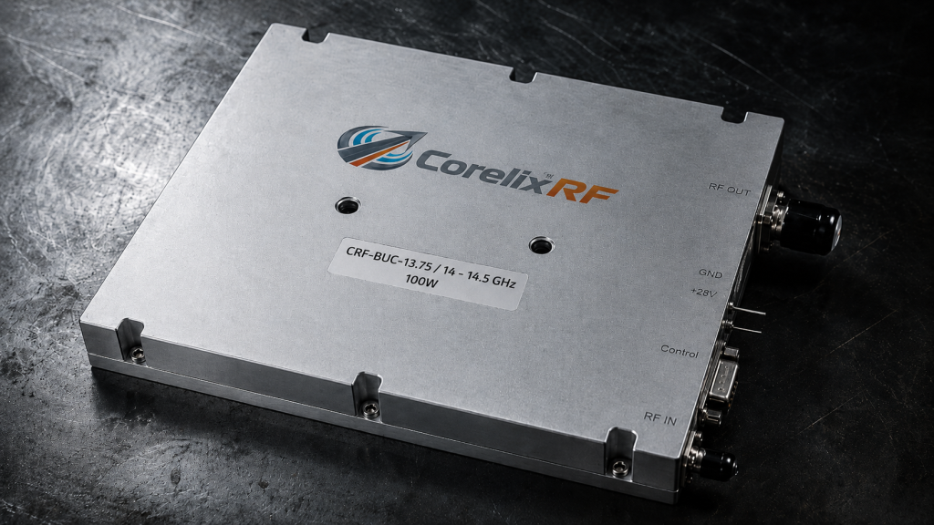
Truth be told. We deliberately designed the rugged CorelixRF Block Upconverter CRF-BUC-Ku-100W specifically to easily survive these incredibly harsh mobile deployment environments. Annoying grounding issues constantly plague standard cheap commercial off-the-shelf hardware. Our dedicated senior engineering team successfully addressed these glaring electrical vulnerabilities directly at the bare printed circuit board level. We firmly implement extremely strict optical galvanic isolation between primary heavy DC power inputs and highly sensitive digital telemetry monitoring circuits. The advanced internal layout architecture intelligently utilizes completely separate heavy copper ground planes for high-power microwave RF amplification and delicate digital logic control. This deliberate physical trace separation permanently prevents massive DC return currents from violently washing over incredibly delicate precision analog-to-digital converters. A highly capable multi-band warfare vehicle requires absolutely uncompromising physical hardware resilience. We consistently deliver that extreme resilience through incredibly rigorous mechanical and advanced electrical design philosophies.
Isolated Power Interfaces and Communication Ports
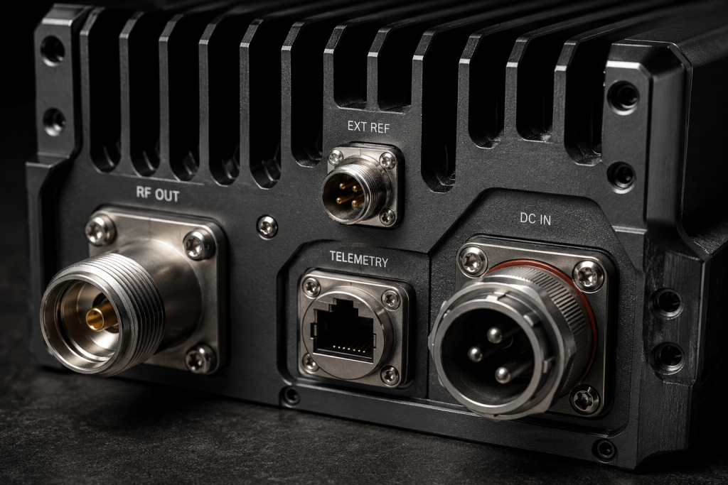
The robust CRF-BUC-Ku-100W specifically utilizes a highly rugged three-pin aviation mating connector for safe power delivery. This specialized heavy interface easily handles the massive 450 W typical power consumption safely without generating any excessive contact resistance. We carefully route the sensitive Ethernet monitoring data connections completely through a distinctly separate sealed aviation RJ45 interface. Fast internal digital optocouplers completely electrically isolate these fragile data lines from the noisy main external chassis ground. If the heavy vehicle frame electrical potential shifts violently during a massive RF transmission, those dangerous voltage spikes physically cannot ever reach your delicate central control router. This strict hardware isolation guarantees absolutely continuous telemetry data flow even under extremely severe external electrical stress. It permanently completely prevents those incredibly frustrating system false alarms randomly triggered by noisy common-mode ground interference.
Mechanical Grounding Integrity
Heavy hardware packaging fundamentally dictates long-term deployment grounding reliability. The exact physical package size measures precisely 225 × 151 × 141 mm. Its incredibly rugged milled aluminum housing weighs exactly 5.5 kg. We painstakingly mill the entire external chassis from solid metal blocks to absolutely guarantee totally uninterrupted high-frequency surface conductivity. The strict official IP65 rating guarantees absolutely complete environmental protection against fine dust and corrosive water ingress. This superior environmental rubber sealing safely prevents harsh coastal salt spray from slowly corroding main internal ground connection points. Large external mechanical mounting flanges constantly provide maximum conductive surface area physical contact directly against your vehicle equipment rack. A dedicated heavy grounding stud securely guarantees a highly reliable low-impedance path directly toward the primary central earth bus. The tough unit operates incredibly reliably from extremely cold -40 to blisteringly hot 60 degrees Celsius.
| Parameter | Specification | Note |
| RF Frequency Range | 13.75 / 14 GHz – 14.5 GHz | Ku-Band spectrum |
| Rated Output Power | 50 dBm / 100 W | High power density |
| Input/Output VSWR | 1.5:1 / 1.35:1 | Excellent matching |
| RF Connectors | Input: N-F, Output: WR75 | Standard interfaces |
5. What Are The Best Practices For Multi-Band Vehicle Grounding?
● Implementing Star Grounding Topologies
● Choosing Proper RF Connectors and Cables
Here is the bottom line. You simply cannot ever blindly rely on random rusty chassis bolts for critical high-current electrical return paths. Professional system integrators must absolutely adopt highly deliberate strict grounding strategies during initial complex vehicle outfitting. A meticulously planned single-point star grounding electrical topology firmly represents the absolute gold standard for reliable multi-band field installations. Every single major electronic subsystem must securely connect directly back toward one massively thick central copper bus bar using dedicated incredibly heavy-gauge insulated cables. Never lazily daisy-chain heavy DC power returns between multiple different high-power RF amplifiers. Lazy daisy-chaining absolutely guarantees terrible common-mode voltage interference randomly crossing your entire communication array. You must consciously treat all ground return paths with exactly identical extreme respect normally safely given to active high-frequency signal routing.
Implementing Star Grounding Topologies
Carefully start by securely installing a massive thick copper ground bus physically near your primary main power distribution unit. Patiently run individual, precisely equal-length heavy ground cables from each expensive RF module directly straight into this specific central bus. The premium CorelixRF Block Upconverter intelligently includes specific threaded mounting terminals specifically designed for large heavy lug attachments. Generously apply highly conductive chemical anti-oxidant joint compound thoroughly across all bare mechanical mating surfaces right before heavily torquing down the steel bolts. This sticky chemical barrier effectively prevents long-term destructive galvanic corrosion in extremely humid tropical environments. We absolutely highly recommend strongly using flat braided copper ground straps instead of round solid copper wires for critical RF applications. Flat braided straps distinctly offer vastly lower electrical impedance at extremely high microwave frequencies. They successfully easily manage those incredibly fast transient burst currents far better than standard thick circular conductors.
Choosing Proper RF Connectors and Cables
Proper RF connector selection heavily impacts target system grounding integrity. We firmly specify an N-F coaxial input and WR75 waveguide output for absolutely peak maximum performance. The flat WR75 brass flange must perfectly tightly mate against your main dish antenna feed assembly. Any tiny microscopic gaps here easily create massive dangerous RF leakage and terrible localized electrical ground loops. Always use extremely high-quality, fully double-shielded flexible coaxial cables for your critical IF Frequency Range of 950 MHz – 1450 / 1700 MHz. Carefully meticulously terminate all outer cable shields properly at both far ends. Poorly cheaply crimped N-type connectors lazily introduce horrible series resistance directly straight into the sensitive main signal path. This added resistance severely degrades the required small signal gain of ≥68 dB. A beautifully clean, totally continuous outer shield effectively guarantees your critical transmit and receive in-band noise firmly remains completely ≤-76 dBm/Hz. You cannot ignore these details.
| Practice | Implementation Method | Engineering Benefit |
| Topology | Single-point star ground | Eliminates common-mode loops |
| Material | Braided copper straps | Lowers high-frequency impedance |
| Protection | Anti-oxidant compound | Prevents galvanic corrosion |
| Shielding | Double-shielded coax | Reduces RF leakage |
System poor electrical grounding directly inevitably causes incredibly frustrating random false triggers across complex multi-band warfare vehicle platforms. Heavy high current returns actively aggressively interfere with highly sensitive weak control current pins. Successfully resolving this completely requires incredibly strict adherence to proper single-point star grounding topologies and advanced differential oscilloscope diagnostic techniques. Utilizing properly internally isolated premium hardware like the CorelixRF CRF-BUC-Ku-100W permanently completely eliminates these terrible field deployment nightmares. Stop uselessly fighting phantom VSWR alarms today. Immediately upgrade your underlying vehicle electrical integration architecture now. Quickly contact our senior factory engineering team to formally request complete test data and detailed pattern files for your upcoming next critical project review.
Q1: What is common-mode voltage interference?
Common-mode voltage interference occurs when massive high return currents generate a dangerous voltage drop across a seemingly shared electrical ground plane. This sudden potential shift rapidly violently disrupts highly sensitive digital logic pins.
Q2: How does a star grounding topology work?
A meticulous star grounding topology perfectly connects every single individual hardware component directly straight back into one massive central ground bus. This deliberate physical layout securely prevents multiple different expensive devices from improperly sharing the exact same return path.
Q3: Why do we use differential probes for field testing?
Standard cheap oscilloscope probes foolishly solidly reference the main AC earth ground, instantly actively creating terrible secondary loops. Differential active probes accurately precisely measure the exact dynamic potential difference existing between two specific test points without dangerously introducing completely external ground references.
Q4: What causes false VSWR alarms in mobile units?
Incredibly fast high current transients violently heavily elevate the local board ground potential physically near highly sensitive internal analog-to-digital converters. The confused central microcontroller instantly blindly reads this massive voltage spike exactly as a severe critical system fault and immediately violently triggers a totally false alarm.
Q5: How does the CRF-BUC-Ku-100W handle power fluctuations? It specifically uses completely highly isolated internal heavy copper ground planes and fast optical optocoupled telemetry data lines. This advanced rugged hardware design intelligently permanently physically separates the incredibly heavy 450W typical power consumption paths directly safely away from the fragile RJ45 communication interface.