
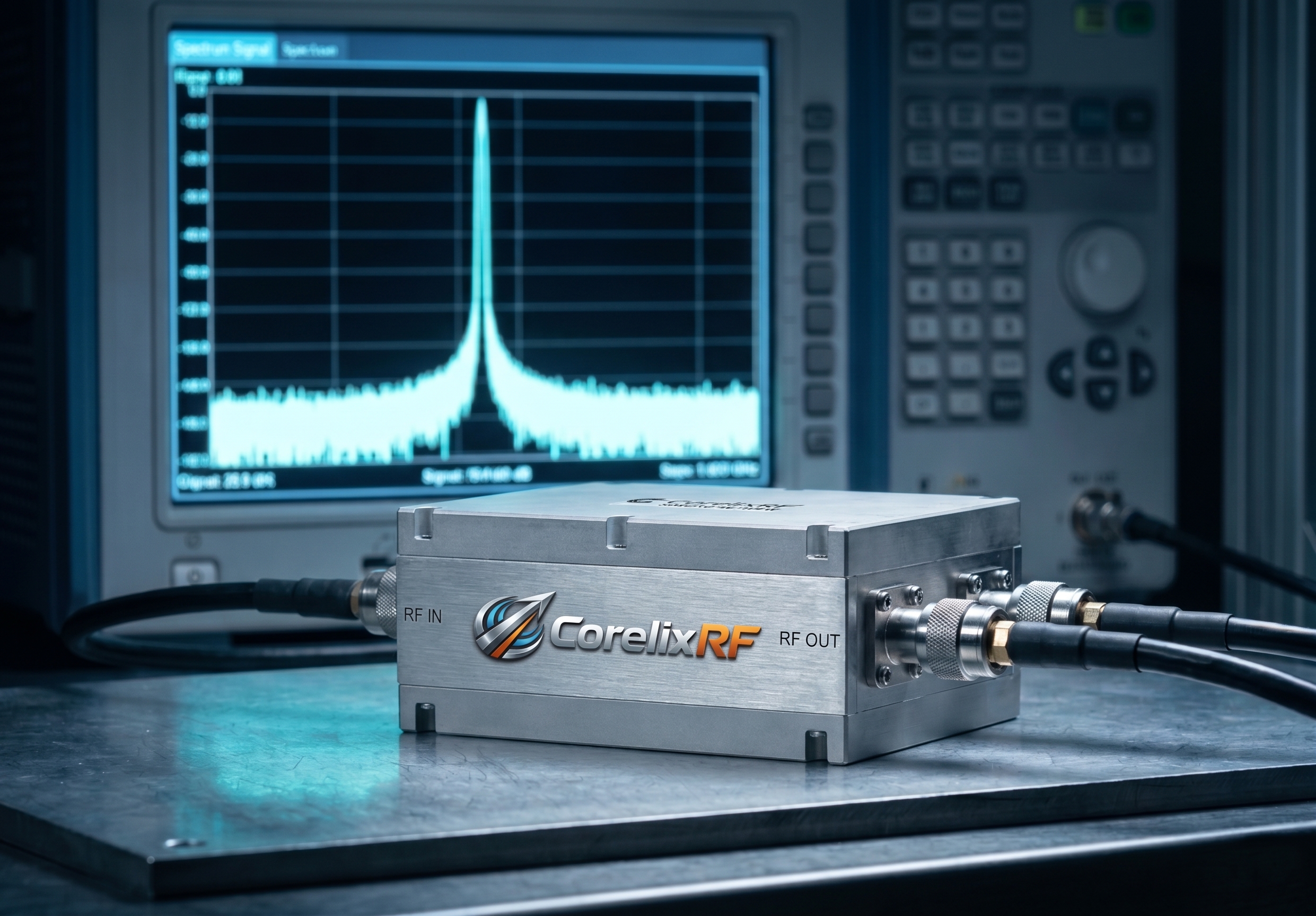
High-precision radar sources frequently suffer from unexplained detection range degradation during live-fire exercises or continuous surveillance operations. System engineers routinely blame atmospheric conditions or antenna misalignment when the radar module fails, completely ignoring the internal direct current distribution architecture. A poorly filtered switching supply injects destructive low-frequency noise directly into the amplification stages, driving up the noise floor and masking weak return signals. This parasitic modulation generates false targets, degrades Error Vector Magnitude (EVM), and pushes sensitive gallium nitride components toward catastrophic thermal runaway. Without proper hardware defense, these spurious emissions compromise the entire defense perimeter. CorelixRF engineers approach this physical vulnerability through strictly controlled mechanical and electrical isolation, ensuring the amplifier maintains laboratory-grade spectral purity regardless of the raw direct current input quality.
Why Does High-Precision Radar Source Detection Range Shrink in Field Operations?
Consider the physical reality Field deployments expose radar systems to fluctuating generator power, causing the primary switching power supply to struggle with load regulation and directly answering the question: High-precision radar source detection range shrinking? Check switching power supply ripple-induced RF spurious noise floor elevation. When the direct current bus voltage oscillates even by a few millivolts at frequencies between 100 kHz and 1 MHz, these variations ride directly on the drain voltage of the final amplifier stages. The active devices operate as unintentional mixers, modulating the primary continuous-wave or pulsed radio frequency signal with the low-frequency direct current ripple. This modulation creates sidebands, effectively raising the noise floor across the entire operating bandwidth. As the noise floor climbs, the signal-to-noise ratio drops proportionally, blinding the receiver module to distant or low radar cross-section targets. Engineers measuring a three-decibel rise in the noise floor will observe a direct geometric reduction in the maximum detection distance, confirming the exact failure mechanism of the physical hardware under operational stress.
How Does Switching Power Supply Ripple Elevate the RF Spurious Noise Floor?
The fundamental physics dictate that any non-linear device will multiply input frequencies, and a radio frequency transistor operating near saturation is highly non-linear by design. Standard commercial switching power supplies utilize pulse-width modulation to regulate their output voltage, inherently generating high-frequency switching transients and localized magnetic fields. When a power supply lacks sufficient output filtering, these transients travel along the wiring harness, bypassing standard decoupling capacitors due to parasitic inductance. Upon reaching the amplifier’s bias circuits, the ripple amplitude translates into dynamic gain and phase variations. For a broadband module, this means amplitude modulation converts directly into phase noise and spurious emissions. The carrier signal becomes flanked by discrete spurious tones spaced at exactly the switching frequency of the power supply, rendering the clean spectrum completely unusable for precision target tracking.

| Parameter | Commercial Supply Impact | CorelixRF Filtered DC Impact | Resulting Noise Floor Penalty |
| Ripple Voltage (Vpp) | 150 mV | < 5 mV | Up to +12 dBc |
| Switching Frequency | 250 kHz | Suppressed > 60 dB | Intermodulation Spurs |
| Load Transient Recovery | 500 µs | < 10 µs | Pulse Droop > 1.5 dB |
| Parasitic Inductance | > 10 nH | < 1 nH | RF Instability |
What Are the Catastrophic Consequences of Degraded Error Vector Magnitude?
Let’s examine the raw data gathered from our thermal imaging and spectrum analyzer benches during simulated overload conditions. Error Vector Magnitude serves as the primary metric for signal fidelity in complex modulation schemes used by modern phased-array radars. When power supply ripple injects phase and amplitude errors into the transmission path, the constellation points of the transmitted signal smear out from their ideal coordinates. This physical degradation means the receiver cannot properly decode the timing or phase information of the return pulse. Beyond signal processing failures, degraded Error Vector Magnitude indicates that the power amplifier is operating inefficiently, dissipating intended transmission energy as pure waste heat. If left unchecked, this localized thermal stress causes rapid degradation of the transistor’s semiconductor junctions, inevitably leading to a complete breakdown of the device under high-duty-cycle military or industrial operations.
Why Do Standard Commercial Power Supplies Fail at Microwave Frequencies?
Here is the engineering truth Standard commercial power supplies are engineered to illuminate light-emitting diodes or drive industrial motors, not to bias highly sensitive microwave amplification chains. Manufacturers of these generic units prioritize cost reduction and gross efficiency over spectral purity, frequently omitting heavy inductive chokes and employing cheap electrolytic capacitors with high equivalent series resistance. In a microwave environment, the high resistance completely negates the capacitor’s ability to shunt high-frequency noise to the ground plane. Furthermore, generic supplies lack adequate electromagnetic interference shielding, allowing their internal switching transformers to radiate magnetic fields directly into nearby radio frequency cavities. This radiative coupling bypasses any conductive filtering on the line, directly inducing spurious currents into the microstrip transmission lines of the amplifier module, ruining the isolation parameters and destroying the spectral integrity.
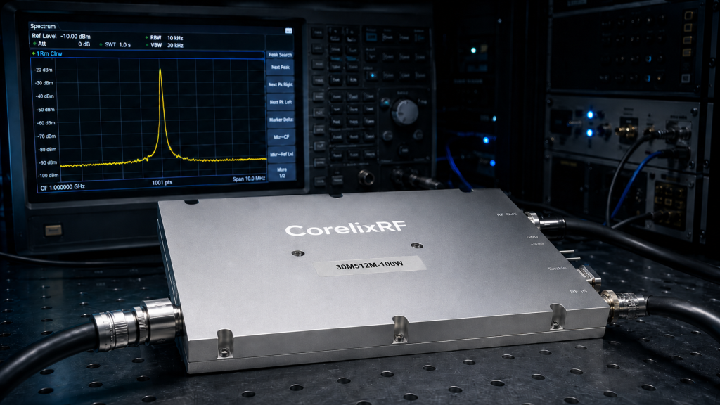
| Component | Standard Commercial Grade | RF-Grade Requirement | Failure Mode in Radar Systems |
| Output Capacitors | Aluminum Electrolytic | Multi-layer Ceramic (MLCC) | High ESR causes ripple pass-through. |
| Inductors | Unshielded Ferrite Core | Fully Shielded / Potted | Magnetic coupling into RF circuits. |
| Enclosure | Thin Stamped Aluminum | CNC Milled Billet Aluminum | Radiated EMI leaks into antenna. |
| Transient Suppression | Basic Varistor | Ultra-fast TVS Diode Array | Overvoltage destroys GaN HEMT. |
How Does Thermal Expansion Exacerbate Impedance Mismatch in Radar Systems?
Consider the physical reality Continuous operation of a high-power amplifier generates massive thermal loads that must be dissipated through the baseplate and heat sink assembly. Dissimilar metals, such as the copper flange of the package, the solder interface, and the aluminum housing, possess vastly different coefficients of thermal expansion. As the system cycles between ambient temperatures and maximum operating thermal limits, these differing expansion rates create immense mechanical shear stress on the solder joints and internal bonding wires. This physical warping alters the microscopic distances between the microstrip traces and the ground plane, fundamentally changing the characteristic impedance of the transmission line. When the impedance deviates from the ideal fifty ohms, reflection occurs, causing voltage standing wave ratio spikes. This reflected power feeds back into the active device, creating localized hot spots and further degrading the linearity of the entire amplification block.
Can Inferior Filtering Components Induce Transistor Burnout Under High Load?
The fundamental physics dictate that energy cannot be destroyed; it can only change form or be dissipated as heat. When inferior filtering components fail to suppress power supply ripple, the resulting low-frequency oscillations interact with the bias networks of the transistors to create low-frequency instability. This instability manifests as massive, uncontrolled current draw from the power supply, known as a sub-harmonic oscillation. The transistor attempts to amplify this unwanted low-frequency energy alongside the intended microwave signal, instantly exceeding its maximum safe operating area. The physical manifestation of this failure is a localized melting of the semiconductor die, carbonizing the surrounding printed circuit board material and rendering the module permanently disabled. CorelixRF design principles strictly mandate the use of distributed, multi-stage low-pass filtering networks using strictly controlled dielectric materials to ensure unconditional stability.
| Dielectric Material | Temperature Coefficient | Dissipation Factor | Stability under RF Load |
| Standard FR4 | Highly Variable | High (0.020) | Prone to thermal drift and failure. |
| Rogers RO4350B | Low (50 ppm/°C) | Low (0.0037) | Excellent for broadband matching. |
| Alumina (Ceramic) | Extremely Low | Very Low (<0.001) | Ideal for high-power networks. |
| Teflon (PTFE) | Moderate | Extremely Low | Used in critical low-loss junctions. |
What Does the Raw Laboratory Data Show Regarding Insertion Loss Spikes?
Let’s examine the raw data generated by our vector network analyzers during the qualification of standard market amplifiers compared to our engineered solutions. When examining the forward transmission coefficient, generic amplifiers often exhibit sharp, unpredictable spikes in insertion loss across their operating bandwidth. These anomalies are not theoretical; they represent physical resonances within the poorly machined cavity or parasitic coupling between adjacent filter stages. An unexpected two-decibel spike in insertion loss at a targeted radar frequency means the system loses nearly forty percent of its transmission power before the signal even reaches the antenna matrix. This severe attenuation forces the system to run hotter to compensate, directly confirming the phenomenon: High-precision radar source detection range shrinking? Check switching power supply ripple-induced RF spurious noise floor elevation. Precision CNC machining remains the only method to guarantee a flat, predictable response across the entire spectrum.
How Does the CRF-PA-30M512M-100W Mitigate Sub-Hertz Phase Noise Anomalies?
Here is the engineering truth The CRF-PA-30M512M-100W operates flawlessly within the most hostile electromagnetic environments, completely negating the effects of dirty power inputs. CorelixRF integrates a proprietary, heavily shielded active bias controller and a multi-stage filtering network directly onto the main board, physically isolating the drain and gate voltage rails from the main input. This architecture provides over sixty decibels of power supply rejection ratio at switching frequencies up to five megahertz. By preventing the ripple voltage from ever reaching the active gallium nitride transistors, the module maintains an ultra-low phase noise profile, ensuring that the transmitted radar pulse remains coherent. This hardware-level defense mechanism guarantees that system integrators will not face arbitrary performance degradation, allowing the processor to reliably identify targets at the absolute theoretical limit of the link budget.
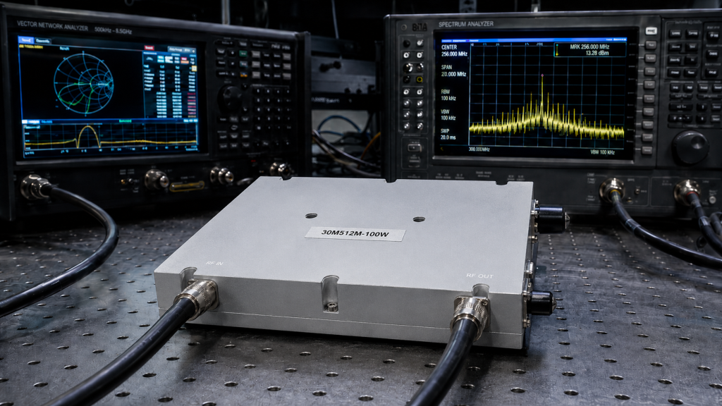
| CRF-PA-30M512M-100W Spec | Verified Laboratory Value | System Level Benefit |
| Frequency Range | 30 MHz to 512 MHz | Supports wideband frequency hopping. |
| Output Power (CW) | 100 Watts (Minimum) | Guarantees maximum detection range. |
| Input VSWR Tolerance | 3:1 Continuous | Survives severe antenna mismatch. |
| DC Input Filtering | Active Bias Control | Eliminates power supply ripple spurs. |
Why Is Strict Mechanical Tolerance Vital for Amplifier Hardware Defense?
Consider the physical reality At high frequencies, the physical dimensions of the mechanical enclosure act as an integral part of the electronic circuit. If the machining tolerances of the aluminum housing deviate by even a fraction of a millimeter, the cavity inadvertently acts as a waveguide, fostering internal feedback loops that destroy the amplifier’s stability. CorelixRF machines every housing for the CRF-PA-30M512M-100W from solid billets of aircraft-grade aluminum, maintaining tolerances tighter than two-hundredths of a millimeter. This stringent mechanical control ensures optimal ground plane continuity, prevents leakage between amplifier stages, and guarantees maximum surface area contact for thermal transfer. When generic modules use cheap, cast-aluminum enclosures with poor surface finishes, the resulting gaps cause micro-arcing and grounding loops, injecting further noise into the system and proving that mechanical engineering is indistinguishable from electrical engineering in microwave manufacturing.
| Mechanical Parameter | Tolerance Strictness | Physical Impact on RF Performance |
| Baseplate Flatness | < 0.001 inches per inch | Prevents thermal bottlenecks and hot spots. |
| Cavity Dimensions | ± 0.02 mm | Stops unwanted cavity resonances. |
| Connector Torque | Precisely Calibrated | Maintains 50-ohm match, minimizes loss. |
| Shielding Gaskets | Conductive EMI Elastomer | Blocks external electromagnetic interference. |
How Can System Integrators Verify Actual Performance Against Stated Specs?
The fundamental physics dictate that a specification sheet holds zero value without empirical verification using calibrated, traceable test equipment. System integrators must demand comprehensive test reports that include swept-frequency measurements for gain, return loss, and most importantly, spurious emissions while operating under heavily rippled direct current power. Testing must be conducted using a directional coupler, a high-power attenuator, and a modern spectrum analyzer capable of measuring wideband noise floor variations. To properly diagnose signal degradation, engineers must inject a known ripple voltage into the feed and observe the resulting intermodulation products in real-time. CorelixRF provides these exact, raw data plots with every production batch of the CRF-PA-30M512M-100W, offering complete transparency into our manufacturing tolerances and demonstrating absolute adherence to the unyielding principles of engineering truth.
The physical reality of microwave engineering leaves no room for ambiguous claims or inferior hardware architectures. When deploying high-stakes radar infrastructure, ignoring the quality of direct current power filtering guarantees catastrophic system failure and severely reduced operational capacity. The CRF-PA-30M512M-100W from CorelixRF eliminates spurious noise floor elevation through uncompromising physical defense mechanisms, precision machining, and laboratory-verified signal integrity. Stop accepting degraded performance due to generic components and unverified specifications. Contact the CorelixRF engineering team today to request the full technical Data Sheet and secure your system’s operational reliability.
FAQ
Q1: Why does replacing the antenna not fix the radar range issue?
Replacing the antenna only addresses the passive radiation element of the system. If the internal power amplifier is modulating the signal with direct current ripple, the antenna will simply broadcast the corrupted, noisy signal with higher efficiency. The root cause lies in the active amplification stage and the quality of the incoming power supply, requiring physical hardware defense at the component level.
Q2: Can we use external DC filters instead of the CRF-PA-30M512M-100W?
External filters add parasitic inductance to the wiring harness and fail to stop radiated electromagnetic interference from bypassing the conductive path. The CRF-PA-30M512M-100W integrates the filtering directly onto the microstrip substrate, completely eliminating the distance between the suppression network and the vulnerable transistor gate, guaranteeing maximum rejection.
Q3: How does CorelixRF test the CRF-PA-30M512M-100W for thermal stability?
CorelixRF mounts the module on a thermally controlled baseplate and subjects it to maximum continuous wave output power while sweeping the ambient temperature across the specified operational limits. We continuously monitor the insertion phase and gain parameters using a vector network analyzer to ensure the mechanical expansion does not degrade the internal fifty-ohm matching networks.
Q4: What is the exact failure mechanism of GaN transistors under high ripple?
High ripple causes severe amplitude variations, driving the gallium nitride transistor rapidly in and out of deep compression. This violent switching generates localized thermal spikes in the semiconductor lattice that exceed the dissipation rate of the baseplate, leading to metal migration, gate leakage, and ultimately, a catastrophic short circuit across the device junction.
Q5: Where can I download the exact mechanical STEP files for integration?
System integrators and mechanical designers can acquire the precise 3D mechanical STEP models by directly contacting the CorelixRF technical support team. We provide exact dimensional data, center of gravity metrics, and thermal dissipation requirements to ensure flawless integration into your specific chassis or radar enclosure.
Define pulsed amplifier protection and test evidence early
Pulsed amplifier projects should specify pulse width, duty cycle, peak and average power, load condition, protection timing, recovery behavior, cooling limit and required FAT curves before hardware selection.
Recommended next step: send the operating band, output power target, duty cycle, load condition, control interface, protection or thermal limits and required FAT documents. CorelixRF can review this How to Lower the RF Spurious Noise Floor in Radar Systems? requirement against standard RF amplifier platforms, RF front-end options and controlled customization paths.