
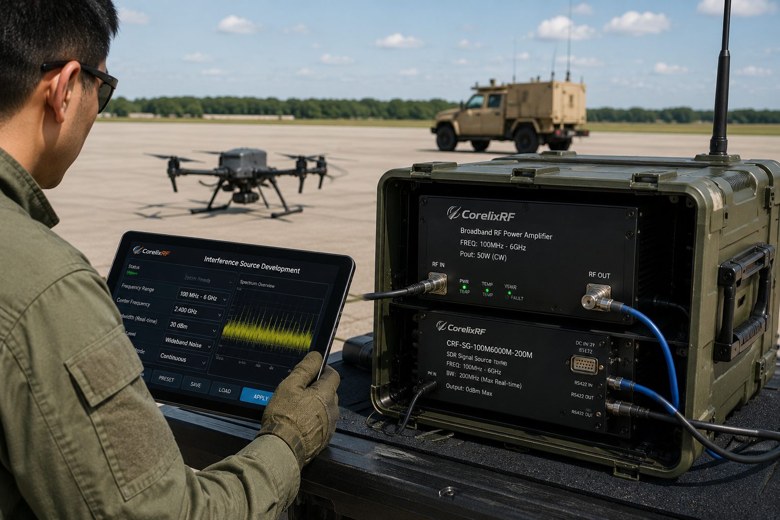
A 100 MHz to 6 GHz SDR signal source module is often selected when a test system needs programmable RF stimulus without building the entire source chain from separate synthesizer, modulator, controller, and interface blocks. CorelixRF CRF-SG-100M6000M-200M is specified as a Wideband SDR Digital RF Source Module covering 100 to 6,000 MHz, with 200 MHz maximum real-time bandwidth, maximum output power greater than 0 dBm, not specified as amplifier gain; output dynamic range is greater than 25 dB, and a compact 60 x 140 x 14 mm outline. It is a practical candidate for engineers planning RF test integration, signal simulation, interference-source development, and compact SDR-controlled platforms.
When buyers compare a wideband RF signal source to a lab-only signal generator, the important question is not only frequency coverage. Integration teams also need to review output range, control interface, power supply, physical envelope, output connector, frequency accuracy, and out-of-band suppression before the module is designed into a system.
Why a Wideband SDR Source Needs System-Level Review
The 100 to 6,000 MHz range overlaps many RF benches, communications test paths, receiver checks, and stimulus chains. A compact source module can reduce integration size, but it also pushes responsibility onto the system designer. The receiving chain, amplifier stages, filters, attenuators, antennas, and monitoring instruments must all be chosen so the source can operate inside a controlled and repeatable signal path.
The datasheet lists SMA RF output connector, output VSWR below 2.5, output dynamic range greater than 25 dB, frequency accuracy below 0.1 MHz, and out-of-band suppression greater than 40 dB. Those values should be translated into the final test plan. For example, a receiver test bench may care about repeatable level setting, while a system-level RF simulation platform may care more about bandwidth, control timing, and signal routing.
Key Specifications for CRF-SG-100M6000M-200M
CorelixRF CRF-SG-100M6000M-200M is specified for 100 to 6,000 MHz operation and 200 MHz maximum real-time bandwidth. Maximum output power is listed as greater than 0 dBm, output power variation is below 1 dB, and standby power is below 5 W. The module uses 9 to 32 VDC supply, current consumption up to 0.5 A at 9 V, standby power below 5 W. It also lists RS422 for both the upgrade interface and communication interface, with built-in multiple interference sources.
These specifications make the module useful for RF test platforms where space, supply flexibility, and control integration matter. Engineers planning a signal chain validation setup should define the required output level at the next stage, then add the expected loss from cables, switches, attenuators, and filters. If a downstream power amplifier is used, source output limits and protection logic should be defined before high-power testing begins.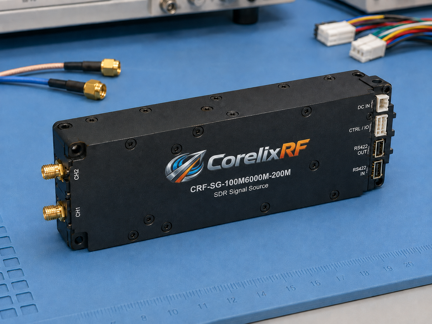
Mechanical and Interface Planning
The package size is 60 x 140 x 14 mm, and the weight is less than 0.2 kg. The RF output is SMA, while power and control are handled through DC input and RS422 interfaces. This small mechanical envelope can help embedded integration, but it also requires careful planning for connector access, cable retention, grounding, thermal environment, and service access.
A good RFQ should request the final outline drawing, pin assignment, command details, and any supported waveform or source configuration information. The datasheet notes that the mechanical outline is kept visible for dimensional review and connector confirmation. That is useful for teams trying to place the module in an enclosure before all control software is finalized.
Use Cases for RF Test and SDR Integration
The strongest fit is a controlled RF stimulus path where the source module is part of a larger bench or embedded system. Possible use cases include receiver stimulus, communications-path validation, RF simulation, ATE fixtures, and compact test equipment. For teams that have seen RF signal anomalies during integration, the source module should be reviewed along with cabling, grounding, shielding, downstream gain, and software control timing.
Procurement teams should avoid asking only for a frequency range. A useful request should state target signals, real-time bandwidth, output level requirements, control interface, supply limits, environmental conditions, and documentation needs. CorelixRF can then review whether the standard source module is suitable or whether a project-specific integration review is needed.
RFQ Checklist
Before requesting quotation, prepare the operating frequency range, required real-time bandwidth, output level at the next RF stage, modulation or source behavior, control interface, supply voltage, current budget, operating temperature, enclosure limits, and required test data. If the source will drive an amplifier, include the amplifier input limit and any required attenuation or interlock behavior.
It is also useful to define what acceptance means. The acceptance point may be RF output connector level, receiver response, signal bandwidth, out-of-band suppression, or a complete system test. A structured RFQ process helps keep these requirements visible before hardware is ordered.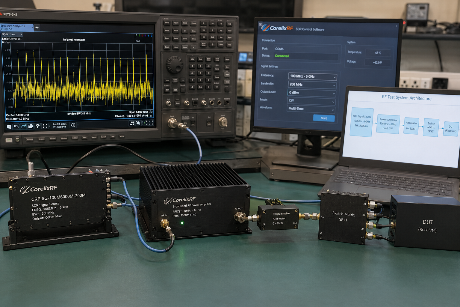
FAQ
What frequency range does CRF-SG-100M6000M-200M cover?
It is specified for 100 to 6,000 MHz operation.
What is the real-time bandwidth?
The datasheet lists 200 MHz maximum real-time bandwidth.
Which interfaces are used?
The RF output connector is SMA. The communication and upgrade interfaces are RS422, and the module operates from a 9 to 32 VDC supply.
Is this an amplifier?
No. It is a wideband SDR digital RF source module. It should be specified as part of the signal generation and control path, not as a high-power output stage.
What should be reviewed before integration?
Review output level, bandwidth, RS422 control, DC supply, enclosure space, cable routing, grounding, downstream gain, and the acceptance test point.